Your hood is doing more than you think — or maybe a lot less than it should be.
For most performance builds, the factory hood is a sealed lid sitting over a heat-soaked engine bay. It traps thermal energy that chips away at power, reliability, and lap times. A vented carbon fiber hood fixes that on two fronts: it pulls weight off the nose where it hurts handling most, and it gives that trapped heat a way out. Not every vented hood works the same way, though. Not every build needs one either. And the difference between a functional scoop and a decorative one is rarely obvious from a product photo. This guide cuts through the noise — covering real-world heat extraction mechanics, weight reduction payoffs, scoop versus vent tradeoffs, and a step-by-step installation walkthrough so you buy right and install it the first time.
What Is a Vented Carbon Fiber Hood (And Why “Functional” Is the Key Word)
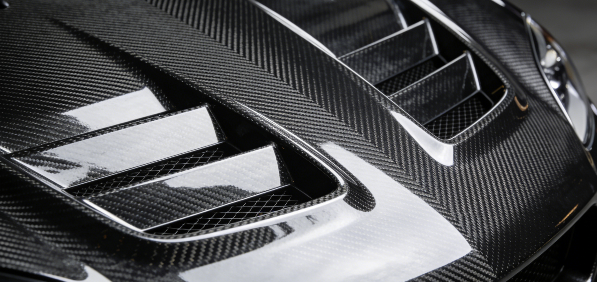
Cut through the marketing language and you’ll find two very different products sharing one name. Only one of them does what it claims.
The functional version has through-holes. Real openings. Air enters the engine bay, moves across it, and exits. The decorative version copies that look using surface textures, raised louvers, or molded-in shapes — but nothing pierces the panel. From twenty feet away, both look the same. Up close, one is an engineering tool. The other is a sticker.
The data is hard to ignore. In controlled testing with a Seibon hood at 84°F ambient, open vents produced IATs of 118–121°F after a 20-minute cruise. Closed vents with rain guards came in at 116–118°F. That 2–3°F gap is noise — not a result. Sealed vents move no air. They just look like they do.
Real extraction hardware tells a different story. RaceLouvers’ stock vent design pulled intake temps down to 111°F minimum — a full 24°F over ambient. That’s a clear airflow path doing real work, not a cosmetic shape pretending to.
Carbon fiber also earns its spot for reasons beyond looks. Its thermal conductivity runs at 0.5–5 W/m·K. Compare that to steel at 15–50 or aluminum at 205–250. Carbon fiber doesn’t soak up heat and dump it back into the engine bay the way metal does. That low conductivity makes it the right base material for a functional venting system.
The numbers back it up. In a documented E92 M3 build, a vented carbon fiber hood produced a 15% drop in engine bay temperatures and cut 30 lbs off the nose of the car.
“Functional” isn’t a marketing upgrade. It’s the spec you confirm before you buy.
Real Weight Savings: What 15–32 lbs of Front-End Reduction Does to Your Car
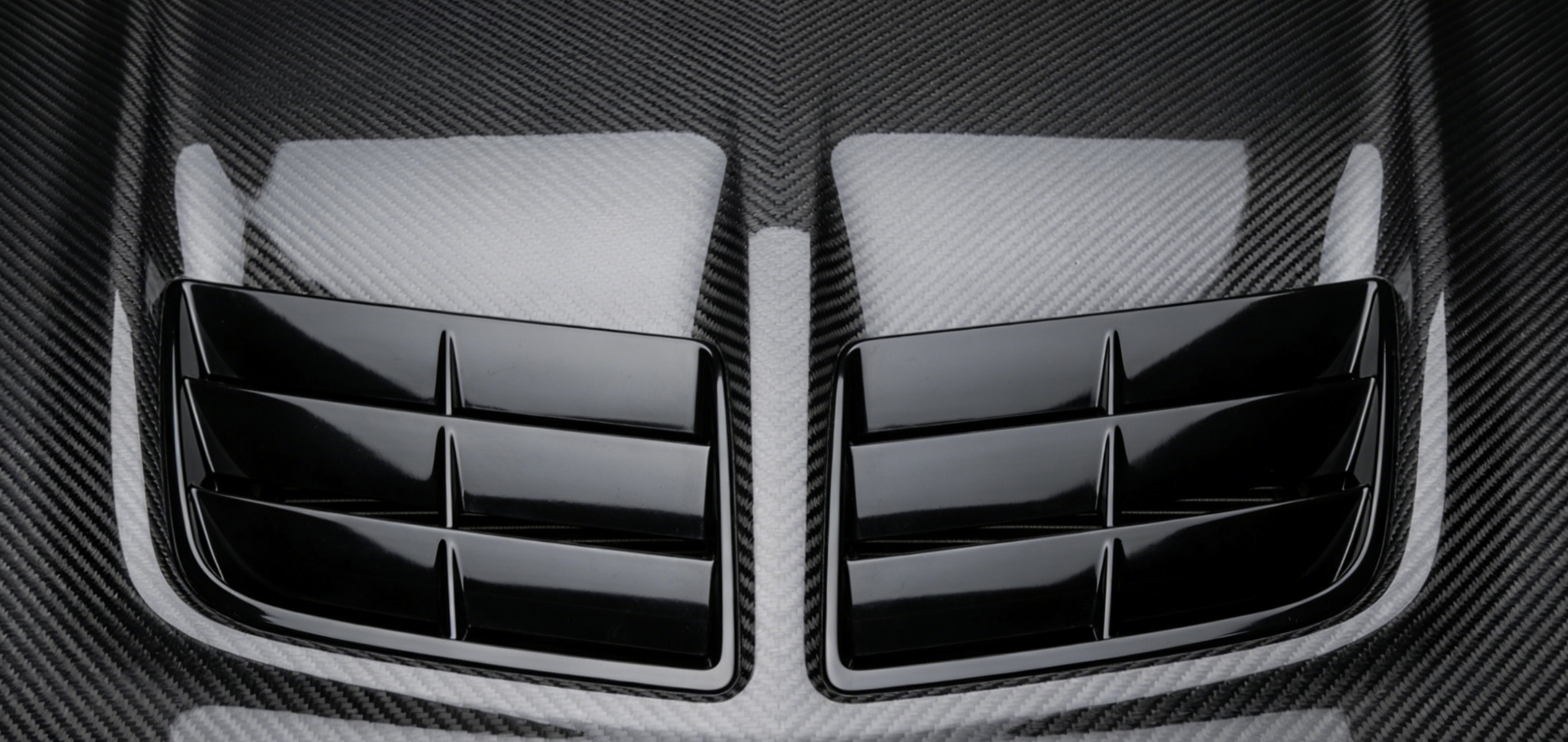
Thirty pounds sounds modest. On a 3,500 lb car, it’s less than one percent of total mass. Strip that weight from the nose — right where a carbon fiber hood pulls it — and the physics change fast.
Front-end mass is the worst kind to carry. It fights steering response, loads the front tires under braking, and raises the center of gravity at the corner that sets your turn-in line. Cutting 15–32 lbs from the front doesn’t behave the same as cutting 15–32 lbs from the trunk. Engineering estimates put the suspension benefit at 2x compared to the same mass removed from a static interior location. Hood weight acts on both the unsprung mass and the rotational dynamics of the front axle. Those two forces hit at the same time.
Here’s what those numbers look like in practice:
-
0-60 mph: A 3,500 lb sedan dropping to 3,468–3,485 lbs gains 0.05–0.1 seconds off the sprint. Small, but real and repeatable.
-
Braking: Less front mass cuts dive and shortens stopping distances. At this scale, expect 1–2 feet off a 60-0 mph stop.
-
Steering feel: Less front inertia sharpens turn-in response by an estimated 1–2%. That’s less about the stopwatch and more about confidence in the first third of a corner.
-
Weight distribution: A typical muscle or turbo street car running 55/45 front bias shifts closer to 54.5/45.5 rearward. That half-percent matters more on corner exit than the number lets on.
Track-class builds show the compounding effect best. Carbon hoods in the 25–40 lb savings range cut front roll by 2–5% and lift mid-corner grip use by 3–5%. Corner speeds climb 1–2 mph. Lap time per technical turn drops 0.2–0.5 seconds. None of that comes from horsepower.
The fuel economy side is quieter but just as consistent. EPA benchmarks link every 100 lbs of removal to a 1–2% MPG gain. For a 15–25 lb hood swap, you’re looking at a 0.15–0.5 MPG real-world improvement. That’s not a marketing claim — it’s a scaled projection from federal test data.
On raw output: every 18.18 lbs removed equals one effective horsepower gained. A 32 lb carbon hood swap adds 1.76 hp before you touch the engine.
The weight number on the spec sheet is just the start. Where that weight comes off is what decides whether you feel it.
How Hood Vents Extract Engine Bay Heat (The Thermodynamics Behind the Upgrade)

Heat doesn’t disappear — it moves. In a sealed engine bay, it has nowhere to go.
Every combustion cycle dumps thermal energy into the air around it. That air sits trapped under a closed hood. It builds pressure. It starts cooking everything nearby — intake sensors, charge pipes, rubber boots. The engine pulls that hot air in and loses power because of it. Intake air temperature rises. Density drops. You’re already losing before you touch the gas.
Vented hoods break that cycle. Two principles make it work.
The first is pressure differential. At speed, air flowing over the hood creates a low-pressure zone above the panel. The engine bay below sits at higher pressure from heat expansion. Open a real vent — not a molded decorative shape — and that pressure gap does the work. Hot air pushes upward through the easiest path out. No fan. No pump. Just physics.
The second is convective flow. Moving air pulls heat away far better than still air. A functional vent doesn’t just release heat — it swaps out stagnant hot air for fresh, cooler air drawn up from below. The engine bay breathes instead of baking.
Vent placement matters just as much as vent size. Exit points near the rear-third of the hood surface sit closest to the peak pressure difference. That position pulls more heat per square inch than forward-mounted louvers working against the airflow direction.
Carbon fiber takes the system further. Steel conducts heat at 15–50 W/m·K. Carbon fiber sits at just 0.5–5 W/m·K. So the hood stops soaking up radiant heat and acting like a second heat source. It becomes a neutral barrier instead. The heat that escapes is the heat you route through the vents — nothing more, nothing less.
That’s not an upgrade. That’s fixing a flaw the factory left in place.
Vented vs Non-Vented Carbon Fiber Hood: Which Build Needs Venting

The answer isn’t universal — and that’s the part most buyers skip.
A non-vented carbon fiber hood still delivers the weight savings. It still looks the part. Street commuters running stock power in a mild climate? Passive insulation handles the heat just fine. The engine bay doesn’t generate enough sustained heat to justify cutting holes in a panel that’s already doing its job.
Add boost, though, and the math changes completely.
Turbo and supercharged builds trap heat at a much higher rate. Pressure builds up inside the engine bay. That’s bad for rubber seals, bad for electronics, and bad for performance. Engineering estimates put the power loss at 10–20% under sustained heat soak. That’s not a small number. That’s power you paid for — and can’t access.
Four Checkpoints Before You Spec a Hood
Go through each one before you decide:
-
Powertrain: Forced induction of any kind makes venting mandatory. Not optional.
-
Track usage: Below 50% track time, a non-vented hood holds up. Above 20% combined track or boost use, you need 62+ sq in of functional open area.
-
Vent count: Street builds need zero to one vent. Daily high-load builds need one to two. Track and forced-induction builds need two to four, placed front-to-rear for maximum heat extraction.
-
Layout logic: Front vents do the primary extraction work. Adding rear or side exits improves total airflow by 20%.
Three conditions tell you venting is non-negotiable. Engine bay temps push past what your radiator and transmission can handle. Boost pressure builds against a sealed hood surface with no way out. Heat stays trapped for more than 20 minutes of continuous load.
Match the vent spec to the build. Not to the look.
Carbon Fiber Hood Scoop vs Hood Vents: Understanding the Difference in Airflow Direction
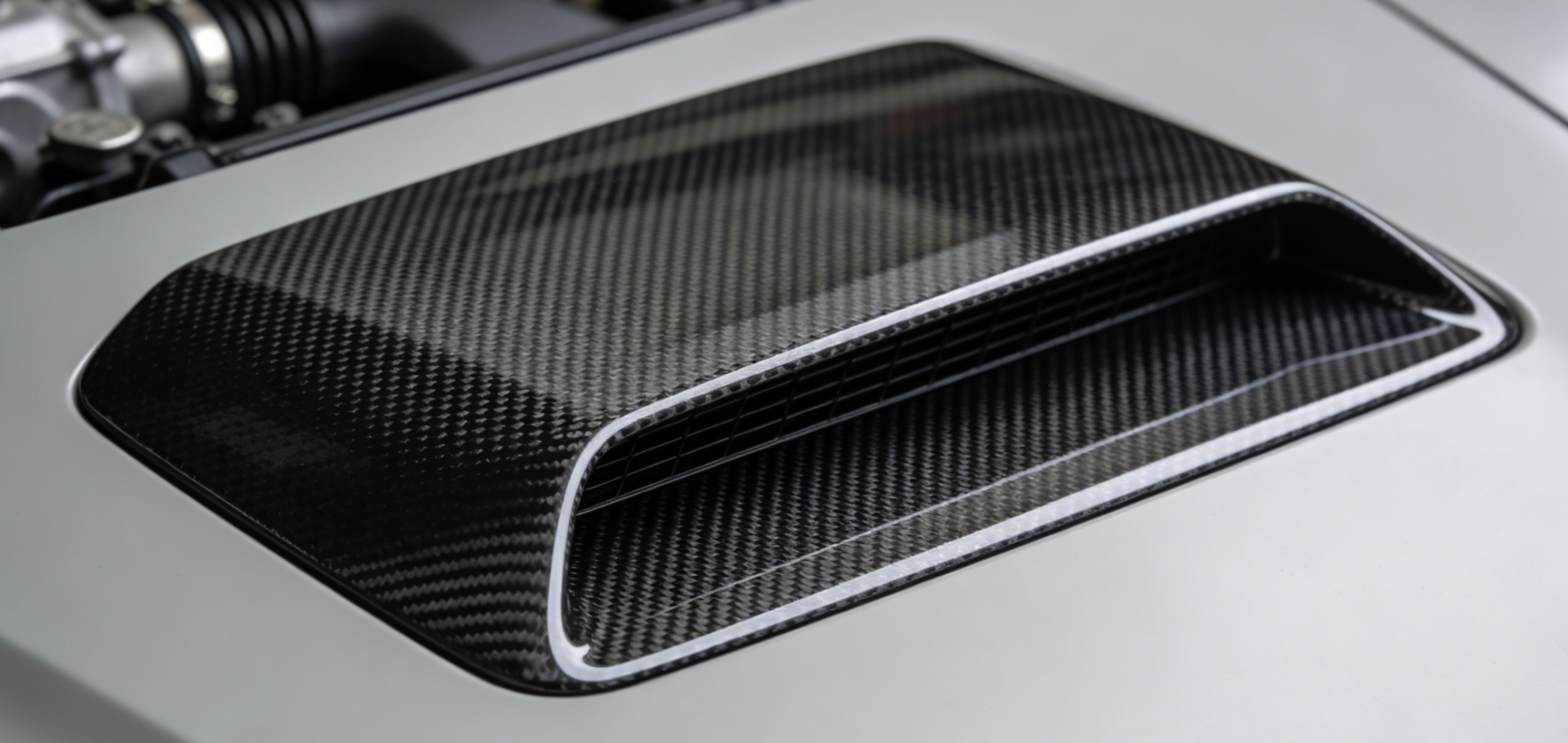
Scoops push air in. Vents pull air out. Most buyers mix these two up — and that’s the core mistake in performance hood design.
They’re not interchangeable. They don’t even solve the same problem. A carbon fiber hood scoop works on positive pressure. It rams cold outside air down into the engine bay, feeding intercoolers and intake systems with denser, cooler charge. A hood vent does the opposite. It creates a low-pressure zone above the panel. That pressure difference drags hot, trapped air up and out. One fills the bay. One clears it.
|
Feature |
Hood Scoop |
Hood Vents |
|---|---|---|
|
Airflow Direction |
Inward (pressurizes bay) |
Outward (depressurizes bay) |
|
Pressure Type |
Positive |
Negative |
|
Primary Function |
Intake boost / intercooler feed |
Heat extraction |
|
Drag Impact |
Increases if unducted |
Reduces underhood turbulence |
The numbers make the gap clear. In Legacy GT testing, a 21×1.6-inch scoop with 33 in² of opening area delivered +20 ft/min of intercooler airflow per 1 mph of vehicle speed — a straight linear gain. That scoop inlet covered 33% of the intercooler’s frontal area, landing right inside Bell’s recommended range. On the hood vent side, the E92 M3 with functional hood vents dropped engine bay temperatures by 15% and shed 30 lbs at the same time.
Neither result happens with the wrong part.
Your Build Might Need Both
Some builds don’t pick one — they run both. The BMW F80 M3 vented carbon fiber hood pairs heat extraction vents with an optional scoop. One panel handles intake efficiency and thermal management at once. WRC-derived designs push this further. Large front-mounted scoop openings ram-feed the intercooler. Rear vent positions push exhaust heat out before it soaks into the bay.
The core idea is straightforward: scoops ram air in, vents push heat out. On forced-induction platforms like the WRX or Legacy GT, running a scoop without underside venting creates spillover pressure and flow separation. Both add drag. Both eat into the efficiency gains the scoop was meant to deliver. The fix isn’t picking one over the other. These two parts work on opposite ends of the same airflow circuit — they’re meant to work together.
Match the hardware to the airflow direction your build needs.
Complete Engine Bay Thermal Management: Pairing Your Vented Hood with the Right Components
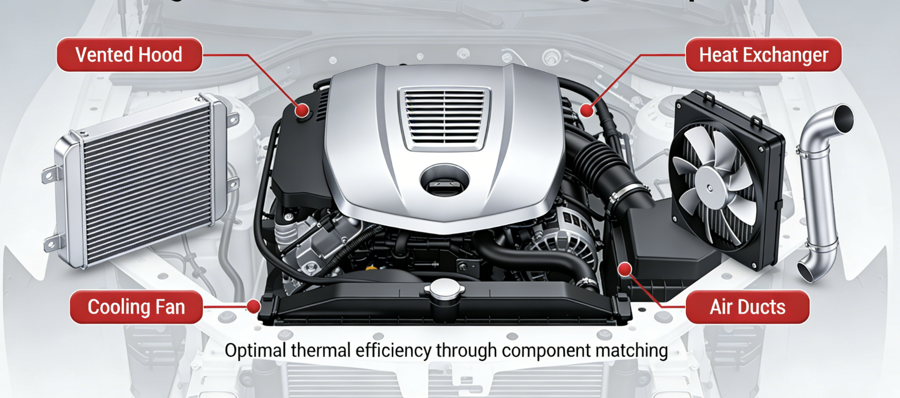
The vented hood is the exit door. But if you haven’t dealt with what’s generating the heat inside, you’ve installed a door in a burning building.
Hood vents create the pressure differential that pulls hot air out. That part works. The problem is ignoring the four or five heat sources still dumping heat inside the bay — exhaust manifolds, turbos, intake pipes sitting inches from cast iron. Each one pushes BTUs into the same air your vents are trying to clear out. You can’t vent your way out of that without tackling the sources head-on.
Here’s the build sequence that works:
1. Exhaust Wrap — Start Here
Wrap the manifolds first. Insulating the exhaust keeps heat trapped inside the exhaust system, where it belongs. You get faster gas escape velocity. Underhood temps drop. The intake pulls from cooler, denser air. This is the single biggest step you can take before the hood goes on.
2. Turbo Blanket — Forced Induction Only
A silica-lined turbo blanket with stainless and silicone reinforcement stops the turbo’s heat from bleeding into the bay. It also holds spool temperature for faster, more consistent power delivery. Skip this on a turbocharged build, and your thermal management is already broken before the engine hits full load.
3. Vented Hood — Pressure Differential Creation
Now the hood does its job right. With exhaust and turbo heat locked down, the vents clear out residual convective heat. They’re not fighting two uninsulated heat cannons pointed at the panel.
4. Cold Air Intake Protection
DEI Reflect-a-Gold tape on intake pipes. 0.0065″ thick, rated for continuous 800°F. It blocks the heat-sink effect — intake tubing absorbs radiant heat and warms the charge before it reaches the throttle body. Cooler air in means more oxygen density and better combustion efficiency.
5. Firewall and Transmission Barriers
Aluminized heat barriers on the firewall push radiant heat away from the cabin side. Transmission tunnel shields bring lower bay temps down. These are secondary gains — real, but not your starting point.
Real-world NACA duct testing confirmed the compounding effect. Intake temperatures that used to recover at a crawl after boost came back to baseline “much much faster” after functional venting was in place. Rear hood vents dropped footbox temperatures within one hour — and you could measure it. Leaf blower tests at turbo blanket locations confirmed active airflow. The pressure differential was doing its job.
One constraint worth knowing: hood vents without matching ducting and heat source insulation show limited results on their own. The vent is the final step in a system, not the whole system.
On naturally aspirated builds, the turbo blanket drops off the list. Focus on exhaust wrap, the vented hood, and intake pipe protection. Firewall barriers give you marginal gains without forced induction heat loads pushing underhood temps into critical territory.
The hood is doing its part. Make sure everything underneath is doing its part too.
Step-by-Step Carbon Fiber Hood Scoop Installation: Alignment, Sealing & Common Mistakes
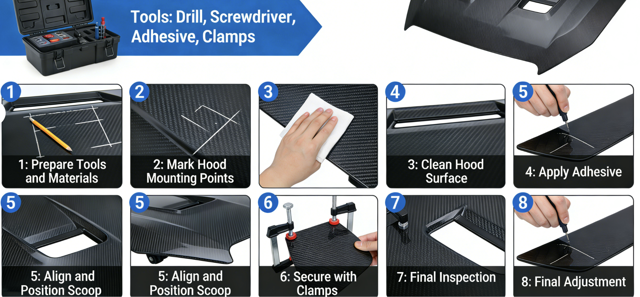
Most carbon fiber hood scoop installations fail in the first five minutes — before a single bolt goes in.
The sequence matters more than the hardware. Get the order wrong, and alignment problems pile up with every step. Get it right, and the whole thing drops into place.
Pre-Install Prep
Pull the OEM scoop first. That means 2–3 heat shield bolts and one T25 Torx center bolt. Once it’s off, check three clearances before the carbon piece gets anywhere near the car: intake manifold position, turbo location if applicable, and oil fill neck height. You need minimum ¼ inch clearance at the fill neck. Any less, and you’ve got a contact problem waiting to happen at road speed.
Dry-fit the carbon scoop next. Don’t torque anything yet. Set it in place and confirm the alignment holes sit flat — no upward tilt at the rear edge.
Tools you need on the bench before you start:
– Allen screws cut ¼ inch longer than OEM for proper thread grab
– 3M tape, Phillips screwdriver, T25 Torx driver
– Dremel with smooth-edge bit, masking tape, vacuum
Alignment SOP
Bolt the hinges with a partner — one person holds, one tightens. Close the hood and read the gaps. One side runs wider than the other? Loosen the hinge bolts, push the hood toward the larger gap, then re-tighten. Adjust bump stops until hood height matches the fenders within ±1/16 inch. Unbolt the striker and reposition it to the carbon hood.
Use 3 front bolts only. The rear 2 holes are open by design — leave them alone. Carbon fiber does not flex like steel. Going past 10–15 ft-lbs risks delamination at the laminate layers. Snug is enough. Do not overtighten.
Sealing & Vent Verification
Run 3M tape along the underside rear clamp after the bolts are set. Clean the surface first. Press the tape flat with no air pockets left underneath.
Check that the vent path is open. Look through the rear of the scoop — the air channel must run clear. No tape should cross the airflow path. Run a water spray test and check for any leak paths into the cabin.
Common Mistakes and Fixes
|
Problem |
Cause |
Fix |
|---|---|---|
|
Scoop tilts upward |
Holes misaligned |
Shimmy hinges side-to-side with wooden block after loosening |
|
Poor latch engagement |
Striker offset |
Adjust 3 bolts: 2 front, 1 rear tied to fender |
|
Heat shield interference |
Not enough clearance |
Dremel-cut indent on sides, smooth edges, vacuum dust |
|
Vent blocked post-seal |
Tape misplacement |
Remove, reapply, confirm channel is open by looking through it |
|
Vibration cracks forming |
Rear bolts over-tightened |
Loosen, add tape layer, monitor laminate flex |
Final fit benchmark: gaps even on all sides with less than 1/8 inch variance, scoop lying flat with zero upward angle at the mounting holes. The panel rocks or lifts at any corner? Go back to the hinge adjustment before calling it done.
Quick-Decision Matrix: Which Vented Carbon Fiber Hood Setup Is Right for Your Build

Three variables determine your setup. Nail all three, and the right answer becomes obvious.
|
Build Type |
Vent Config |
IAT Target |
Priority |
|---|---|---|---|
|
Street Daily |
Closed vents acceptable |
25–30°F over ambient |
Weight savings first |
|
Street Performance |
Mid-hood vents open |
20–25°F over ambient |
Aero + moderate cooling |
|
Track/High-Load |
Extraction vents + radiator ducting |
10–15°F over ambient |
Heat removal critical |
|
Boosted (IS38+) |
Purpose-designed vent + yarn-tuft validated |
Below 30°F over ambient |
Intercooler feed priority |
One number tells you if your cooling setup has a problem. An IAT delta over 30°F above ambient on a street pull means your venting isn’t working. On boosted platforms, that’s not just a warning — it’s a clear diagnosis. Fix it before it costs you power.
Vent placement is the variable most buyers miss. Forward-positioned vents can flip the airflow direction. Air gets pulled backward through the panel instead of out of it. Mid-hood placement fixes that. Run a yarn tuft test to confirm it — don’t wrap up the install without it.
More vents don’t mean better cooling. Two vents in the right spot beat four placed wrong. Position matters far more than count.
Conclusion
Every serious build decision comes down to one question: does this part do something, or does it just look like it does?
A vented carbon fiber hood answers that before you finish asking. You pull real weight off the nose. Heat that kills power and degrades components gets pushed out. Airflow goes where your engine needs it — not just through a hole cut and forgotten.
That’s the gap between a functional upgrade and an expensive sticker.
You have the thermodynamics, the comparison data, and the installation basics. That’s enough to make this call with confidence. Building a weekend track weapon? Great. Running a refined street car that hits harder than it looks? This upgrade fits that too.
Contact HyperX Carbon – Your Trusted Chinese Carbon Fiber Partner
Ready to source high-performance carbon fiber materials or custom forged carbon fiber parts from China?
HyperX Carbon is a leading manufacturer with 20+ years of expertise, specializing in aerospace-grade forged carbon fiber, prepreg, carbon fiber tube, carbon fiber sheet, and lightweight carbon fiber automotive parts/carbon fiber drone components/carbon fiber medical components. We offer:
-
Stable supply chain with premium raw materials (Toray, Mitsubishi, Hengshen)
-
AS9100D certified production for aerospace & UAV applications
-
Rapid prototyping (5-8 weeks) and monthly capacity exceeding 180,000 parts
-
Competitive pricing with 15-18% cost savings on forged carbon solutions
-
Full customization: from T700/T1100G to ultra-high modulus grades
Whether you’re an eVTOL developer, automotive OEM, drone manufacturer, or medical device engineer, HyperX delivers consistent quality, batch-to-batch reliability, and reliable delivery.
Get in touch today for a free consultation, custom quote, or material sample.
📧 Email: [email protected]
🌐 Website: https://www.hyperxcarbon.com/
📞 Phone/WhatsApp: +86 15623270276 (English support available)
Let’s build your next lightweight innovation together – contact HyperX Carbon now and stay ahead in the low-altitude and advanced composites market.