Choosing the wrong carbon fiber material can waste money before production even starts.
A buyer may ask for prepreg when dry fabric is enough. A fabricator may buy carbon fiber fabric without checking resin compatibility. A project team may compare tow, fabric, prepreg, resin, and core materials as if they were interchangeable. They are not.
Carbon fiber is not a single material choice.
It is a material system.
That system can include raw fiber, tow, woven or non-crimp fabric, prepreg, resin systems, core materials, release films, peel ply, vacuum bagging materials, adhesives, and quality-control records. Each material form affects process route, tooling, storage, fiber volume fraction, void risk, surface quality, lead time, and cost.
For buyers, the real question is not only “Which carbon fiber material is strongest?”
The better question is:
Which carbon fiber material form matches the part design, manufacturing process, quality requirement, and purchasing goal?
At HyperX Carbon, we review material selection together with application, tolerance, surface class, load direction, quantity target, and production route. A visible automotive trim part, a CNC-cut UAV plate, a molded bracket, a sandwich panel, and a high-temperature component do not need the same material system.
This guide explains the major carbon fiber materials buyers should understand before RFQ: raw carbon fiber, tow, fabric, prepreg, resin systems, core materials, and auxiliary materials.
Carbon Fiber Materials Explained: What This Guide Covers

Carbon fiber materials are easier to understand when they are viewed as a system rather than a list of isolated products.
A complete carbon fiber material system may include:
-
Raw carbon fiber filaments
-
Carbon fiber tow
-
Woven carbon fiber fabric
-
Non-crimp fabric
-
Spread-tow fabric
-
Carbon fiber prepreg
-
Resin systems
-
Core materials
-
Adhesives
-
Release materials
-
Peel ply
-
Vacuum bagging films
-
Breather and bleeder materials
-
Surface films
-
Material certificates and batch records
Each one plays a different role.
Some materials carry load. Some control resin flow. Some define surface quality. Some support cure. Some make demolding possible. Some protect traceability.
This article focuses on material selection from a buyer and manufacturing decision angle. It does not replace a prepreg product page, fabric and tow product page, resin systems page, molding process article, or traceability checklist.
The boundary is important:
|
Topic |
This Article Covers |
Deeper Page Should Cover |
|---|---|---|
|
Carbon fiber materials |
Material system overview and buyer decision logic |
Materials Hub |
|
Prepreg, fabric, and tow |
Basic role and selection impact |
Detailed prepreg vs fabric vs tow comparison |
|
Resin systems |
Why resin affects cure, Tg, service temperature, and risk |
Full resin systems guide |
|
Core materials |
Why sandwich structures use cores |
Core material product or design page |
|
Auxiliary materials |
Why production materials matter |
Manufacturing process and vacuum bagging pages |
|
Traceability |
Why material records matter |
Full material traceability guide |
The goal is simple:
Buyers should understand how each carbon fiber material affects production before choosing a supplier, asking for a quote, or approving a production route.
What Is Carbon Fiber Material and Why Format Matters
Carbon fiber starts as extremely fine filaments.
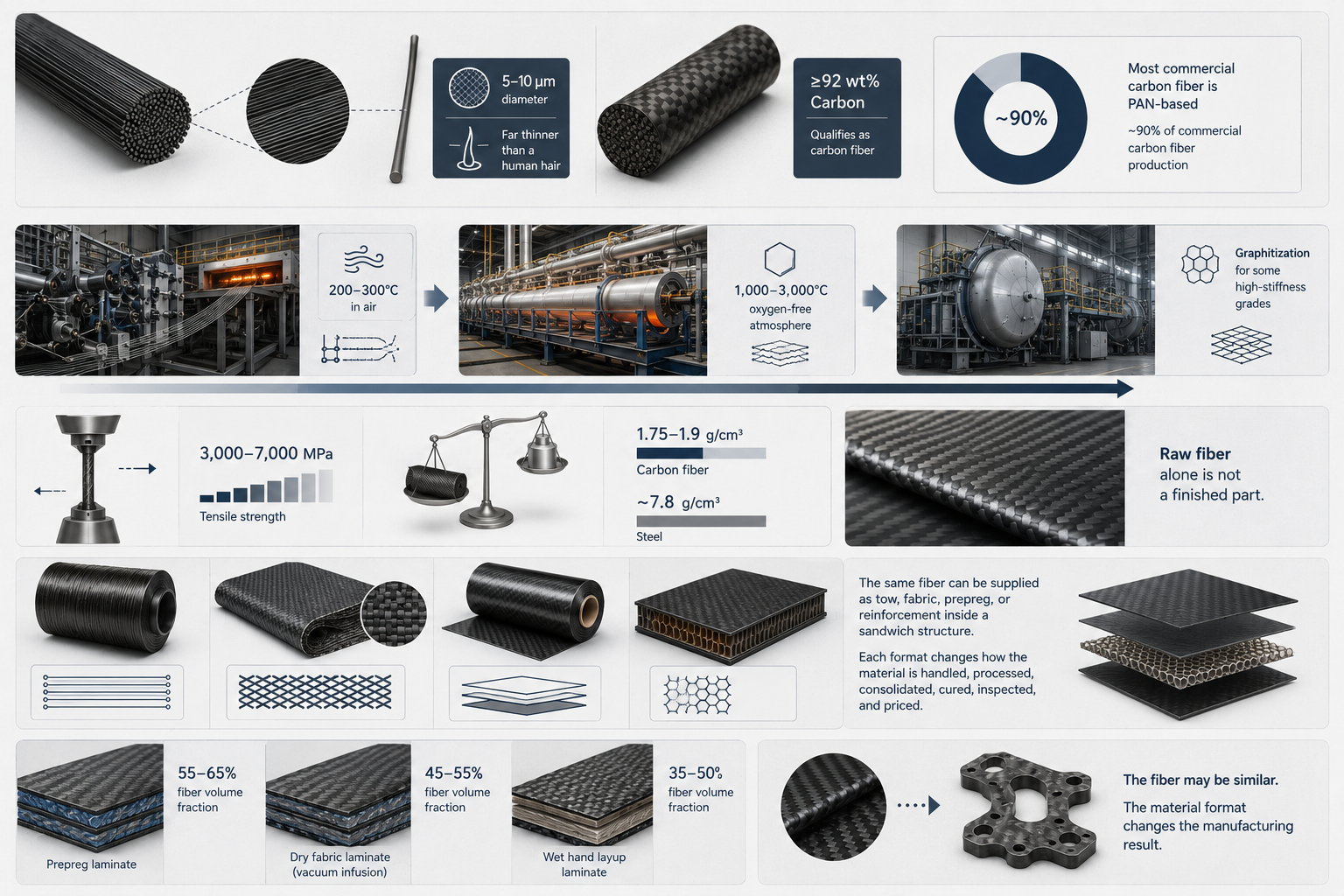
A single filament is usually about 5–10 μm in diameter, far thinner than a human hair. After processing, carbon fiber contains at least 92 wt% carbon, which qualifies it as carbon fiber.
Most commercial carbon fiber is made from polyacrylonitrile, or PAN. PAN-based fiber accounts for around 90% of commercial carbon fiber production.
The production route includes several major heat-treatment steps:
|
Step |
Typical Condition |
Why It Matters |
|---|---|---|
|
Stabilization |
200–300°C in air |
Prepares the precursor for high-temperature conversion |
|
Carbonization |
1,000–3,000°C in oxygen-free atmosphere |
Removes non-carbon elements and forms carbon fiber |
|
Graphitization |
High-temperature treatment for some grades |
Increases carbon ordering and stiffness |
After carbonization, carbon content reaches at least 92 wt%. Some high-temperature routes can push carbon content toward 99 wt%.
Carbon fiber is valued because it combines high strength with low density. Typical carbon fiber tensile strength can range from 3,000–7,000 MPa, while density is around 1.75–1.9 g/cm³. Steel has a density of about 7.8 g/cm³.
That is why carbon fiber can deliver high stiffness and strength at much lower weight.
But raw fiber alone is not a finished part.
The format matters.
The same fiber can be supplied as tow, fabric, prepreg, or a reinforcement inside a sandwich structure. Each format changes how the material is handled, processed, consolidated, cured, inspected, and priced.
For example:
-
A prepreg laminate may reach 55–65% fiber volume fraction under controlled processing.
-
A dry fabric laminate made by vacuum infusion may run closer to 45–55% fiber volume fraction.
-
Wet hand layup may fall around 35–50% fiber volume fraction without strong consolidation control.
-
Autoclave prepreg can achieve very low void content when the process is controlled.
-
Infusion, RTM, and hand layup depend more heavily on resin viscosity, vacuum quality, operator control, and tooling.
The fiber may be similar.
The material format changes the manufacturing result.
Raw Carbon Fiber and Tow: The Foundation of Carbon Fiber Materials
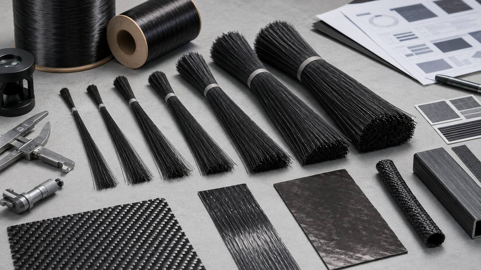
Carbon fiber tow is the building block behind many material forms.
A tow is a bundle of continuous carbon filaments grouped together after carbonization. That tow can later be woven into fabric, spread into thin tapes, impregnated into prepreg, wound onto a mandrel, braided into sleeves, or pulled through pultrusion equipment.
Tow size is usually described by its K value, which means filament count in thousands.
|
Tow Size |
Filament Count |
Typical Linear Density |
Common Use |
|---|---|---|---|
|
1K |
1,000 |
90–120 tex |
High-end cosmetic parts and tight curves |
|
3K |
3,000 |
200–240 tex |
General visible surfaces and structural layers |
|
6K |
6,000 |
300–400 tex |
Mid-size structural components |
|
12K |
12,000 |
400–600 tex |
Larger structural parts and industrial layups |
|
24K |
24,000 |
800–1,200 tex |
Wind blades, pressure vessels, reinforcement |
|
48K+ |
48,000–60,000+ |
≥1,600 tex |
Heavy industrial and infrastructure applications |
K value is not a quality rating.
A 3K tow and a 12K tow made from the same fiber grade can have the same tensile strength and modulus per unit cross-section. The K number mainly describes bundle size, handling behavior, drapability, surface appearance, and processing efficiency.
Smaller tows such as 1K and 3K bend more easily around tight radii and complex surfaces. They are often used where visible weave quality and drapability matter.
Mid-range tows such as 6K and 12K balance structural efficiency, cost, and processing speed.
Large tows such as 24K and 48K+ improve throughput in automated or continuous processes, but they are harder to drape over fine geometry and are less suitable for high-detail cosmetic surfaces.
Tow choice affects process compatibility:
|
Process |
Common Tow Direction |
|---|---|
|
Filament winding |
6K–24K tow is often practical |
|
Pultrusion |
12K–48K tow can build fiber volume efficiently |
|
Weaving and braiding |
1K–12K depends on fabric weight, surface, and geometry |
|
Automated fiber placement |
Tow size depends on equipment, tape width, and design |
For buyers, tow matters because it sits underneath fabric, prepreg, pultrusion, winding, and many custom carbon fiber parts.
When a supplier recommends a material, ask what tow size and fiber grade are being used, not only whether the part is “real carbon fiber.”
Carbon Fiber Fabric: Dry Reinforcement for Layup and Infusion
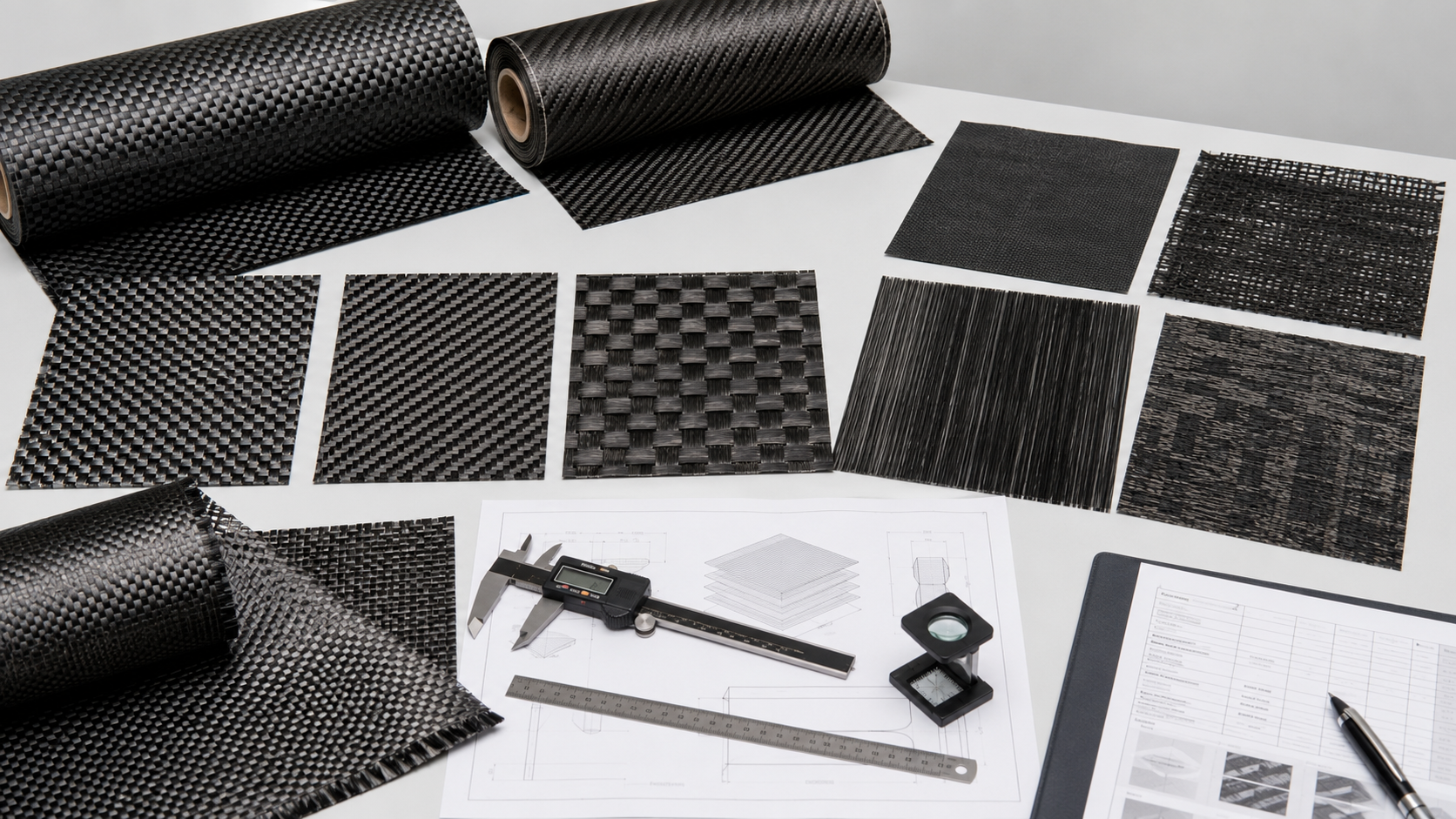
Carbon fiber fabric is dry reinforcement.
It contains carbon fiber but does not include the final resin system unless it is later converted into prepreg. Buyers often choose dry carbon fiber fabric when they want flexibility in resin selection, lower storage complexity, or compatibility with wet layup, vacuum infusion, RTM, or other open and closed mold processes.
Dry fabric is common in:
-
Custom parts
-
Prototype builds
-
Marine components
-
Wind blade structures
-
Automotive panels
-
Industrial covers
-
Large molded shells
-
Non-autoclave production
The main advantage is flexibility.
The buyer or manufacturer can select the resin system, control resin flow, and choose a process route based on tooling, quantity, and performance requirement.
The trade-off is that dry fabric puts more responsibility on the manufacturing process. Resin mixing, resin viscosity, vacuum integrity, infusion path, debulking, consolidation, and cure all affect final quality.
Common fabric forms include:
|
Fabric Type |
Typical Role |
Practical Notes |
|---|---|---|
|
Plain weave |
Stable, tight pattern and regular surface |
More crimp; good handling; common in general layup |
|
2×2 twill |
Better drape and smoother visible pattern |
Common for automotive and visible carbon surfaces |
|
Satin weave |
Smooth surface and lower crimp |
More process-sensitive; useful where surface smoothness matters |
|
Non-crimp fabric |
Straight fibers stitched in orientations |
Better structural efficiency; common in large infused parts |
|
Spread-tow fabric |
Thin, flat tow ribbons with reduced crimp |
Very smooth surface; sensitive to air and resin waviness |
|
Hybrid fabric |
Carbon mixed with aramid or glass |
Improves impact behavior or cost balance |
Areal weight is another key parameter. Lightweight visible layers may be around 200–245 g/m², while structural fabric layers can be much heavier, such as 600–650 g/m² or more depending on design.
Dry fabric process compatibility depends on fabric architecture and resin flow.
|
Fabric Type |
Wet Layup |
Vacuum Infusion |
Typical Target Vf |
|---|---|---|---|
|
Plain weave 200–245 g/m² |
Suitable |
Suitable |
45–55% |
|
2×2 twill 200–650 g/m² |
Suitable |
Suitable |
48–58% |
|
Satin 200–300 g/m² |
Limited |
Suitable with flow planning |
50–58% |
|
NCF 300–1,200 g/m² |
Difficult |
Preferred |
55–62% |
|
Spread-tow 80–200 g/m² |
Not recommended |
High-vacuum process preferred |
52–60% |
|
Carbon/Kevlar hybrid |
Suitable |
Suitable with resin wet-out control |
45–55% |
For buyer decision-making, fabric selection should consider:
-
Geometry
-
Surface requirement
-
Fabric weight
-
Fiber orientation
-
Resin compatibility
-
Infusion behavior
-
Target fiber volume fraction
-
Production quantity
-
Operator skill and process control
Dry carbon fiber fabric is not a lower-quality choice by default.
It is the right choice when the process route, part size, cost target, and production environment match dry reinforcement.
Carbon Fiber Prepreg: Controlled Resin Content for Precision Manufacturing
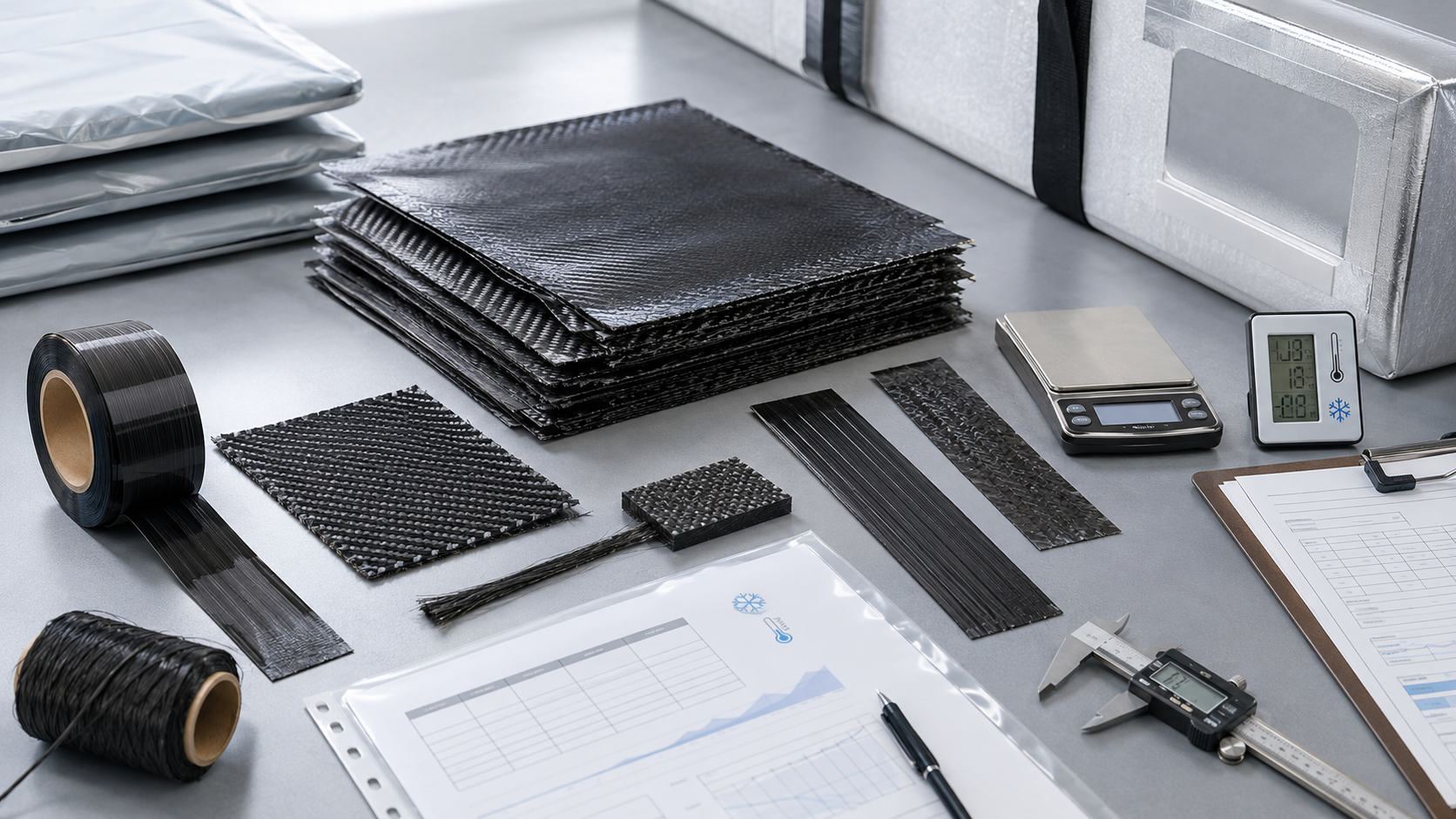
Carbon fiber prepreg is carbon fiber reinforcement that has already been impregnated with a controlled amount of resin.
The resin is partially cured to a B-stage condition. It is solid enough to handle, tacky enough to lay into a mold, and able to complete curing under heat and pressure.
Prepreg reduces guesswork because the resin content is controlled before production. Many carbon fiber prepreg systems use resin content in the range of 30–40 wt%, depending on fiber form, resin system, and application.
Common prepreg formats include:
|
Prepreg Form |
What It Is |
Typical Use |
|---|---|---|
|
Fabric prepreg |
Woven carbon fabric impregnated with resin |
Curved shells, visible panels, quasi-isotropic laminates |
|
UD tape |
Aligned unidirectional fiber impregnated with resin |
Aerospace structures, high-stiffness laminates |
|
Prepreg tow |
Individual impregnated tows |
Filament winding, braiding, automated tow placement |
Prepreg is often selected when buyers need:
-
Tight resin content control
-
Higher repeatability
-
Lower void risk
-
Better laminate consistency
-
Controlled fiber volume fraction
-
High structural performance
-
Cleaner layup
-
Stronger documentation path
Processing route still matters.
Autoclave prepreg curing under external pressure, often around 0.4–0.7 MPa, can achieve very low void content when the process is controlled. Out-of-autoclave prepreg can reduce equipment cost but may accept slightly higher void levels, often around 1–2% for suitable systems and controlled conditions.
Prepreg also has storage requirements.
Most carbon/epoxy prepregs require frozen storage around −18°C. Many systems have room-temperature out-life limits, often around 10–15 days for mid-temperature systems, depending on material grade and supplier specification.
For this overview, the key point is simple:
Prepreg is not automatically the best material. It is the right material when controlled resin content, repeatability, laminate performance, and process discipline justify the storage and tooling requirements.
Detailed prepreg vs dry fabric vs tow selection should be handled as a separate material-form comparison, because the decision depends on equipment, storage, resin content, GSM, tow size, process compatibility, and production volume.
Carbon Fiber Resin Systems: Why Resin Controls Cure, Tg and Service Temperature
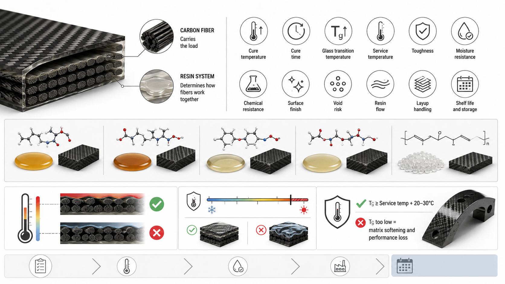
Carbon fiber carries much of the load, but the resin system determines how the fibers work together.
Resin is not just “glue.”
It affects:
-
Cure temperature
-
Cure time
-
Glass transition temperature, or Tg
-
Service temperature
-
Toughness
-
Moisture resistance
-
Chemical resistance
-
Surface finish
-
Void risk
-
Resin flow
-
Layup handling
-
Shelf life and storage
Common carbon fiber resin systems include:
|
Resin System |
Common Role |
Buyer Decision Point |
|---|---|---|
|
Epoxy |
Most common structural composite resin |
Strong balance of performance, processing, and availability |
|
High-temperature epoxy |
Higher Tg and better temperature resistance |
Useful when service temperature exceeds standard epoxy limits |
|
BMI |
High-temperature aerospace and motorsport use |
Higher process demand and cost |
|
Cyanate ester |
Low moisture uptake and high-temperature performance |
Specialized aerospace and electronic applications |
|
Thermoplastic matrix |
Impact resistance, toughness, recyclability potential |
Higher processing temperature and equipment requirements |
For many carbon fiber parts, Tg should sit safely above service temperature. A common engineering rule is to keep resin Tg at least 20–30°C above the expected service temperature.
If the service environment is warm and the resin Tg is too low, the fiber may remain intact but the matrix can soften. That can reduce bending stiffness, ILSS, dimensional stability, and long-term performance.
Resin also affects material format.
For example:
-
Dry fabric requires resin selection during layup, infusion, RTM, or wet layup.
-
Prepreg already contains the resin system.
-
Tow-based winding or pultrusion may use wet resin impregnation or prepreg tow.
-
Sandwich structures require compatibility between resin, skins, core, and adhesive.
This article only introduces the resin system role. A deeper resin systems page should explain epoxy, thermoset, thermoplastic, cure window, Tg, resin content, environmental resistance, and service temperature in more detail.
For RFQ, buyers should send temperature and service-environment requirements early. Resin selection is one of the first places where a cheap material decision can become a performance failure.
Core Materials and Sandwich Structures in Carbon Fiber Parts
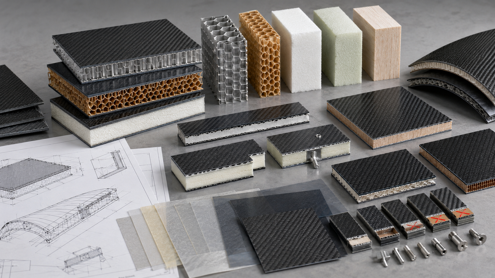
Not every carbon fiber structure is a solid laminate.
Many panels use a sandwich structure: carbon fiber skins on the outside and a lightweight core inside. This design increases bending stiffness without adding much weight.
Core materials are common in:
-
UAV panels
-
Marine decks
-
Automotive panels
-
Aerospace interior panels
-
Robotics covers
-
Medical imaging panels
-
Industrial lightweight structures
-
Large flat or curved carbon fiber panels
Common core material types include:
|
Core Material |
Typical Benefit |
Common Consideration |
|---|---|---|
|
Nomex honeycomb |
Very light and stiff |
Requires careful bonding and edge closure |
|
Aluminum honeycomb |
High stiffness and compression strength |
Conductivity, corrosion, and bonding must be considered |
|
PMI foam |
Good structural foam for composite sandwich panels |
Cost and temperature capability matter |
|
PVC foam |
Useful in marine and industrial panels |
Lower temperature and structural limits than high-end foams |
|
PET foam |
Recyclability and cost balance |
Application-specific strength and processing check needed |
|
Balsa |
Good compression and shear behavior |
Moisture control and natural variation must be managed |
Core materials do not replace carbon fiber. They support the carbon fiber skins by increasing panel thickness and bending stiffness.
A sandwich panel may fail if the core is wrong, even when the carbon fiber skin is acceptable.
Important buyer checks include:
-
Core thickness
-
Core density
-
Compression strength
-
Shear strength
-
Resin compatibility
-
Adhesive compatibility
-
Temperature resistance
-
Moisture sensitivity
-
Edge sealing requirement
-
Insert and fastening design
For carbon fiber panels, the core decision should be reviewed together with load case, bonding area, edge finishing, machining plan, and surface requirement.
At HyperX Carbon, sandwich structure review is especially important for flat panels, UAV structures, medical tables, lightweight covers, and large-area parts where stiffness-to-weight ratio is the main goal.
Auxiliary Materials Used in Carbon Fiber Manufacturing
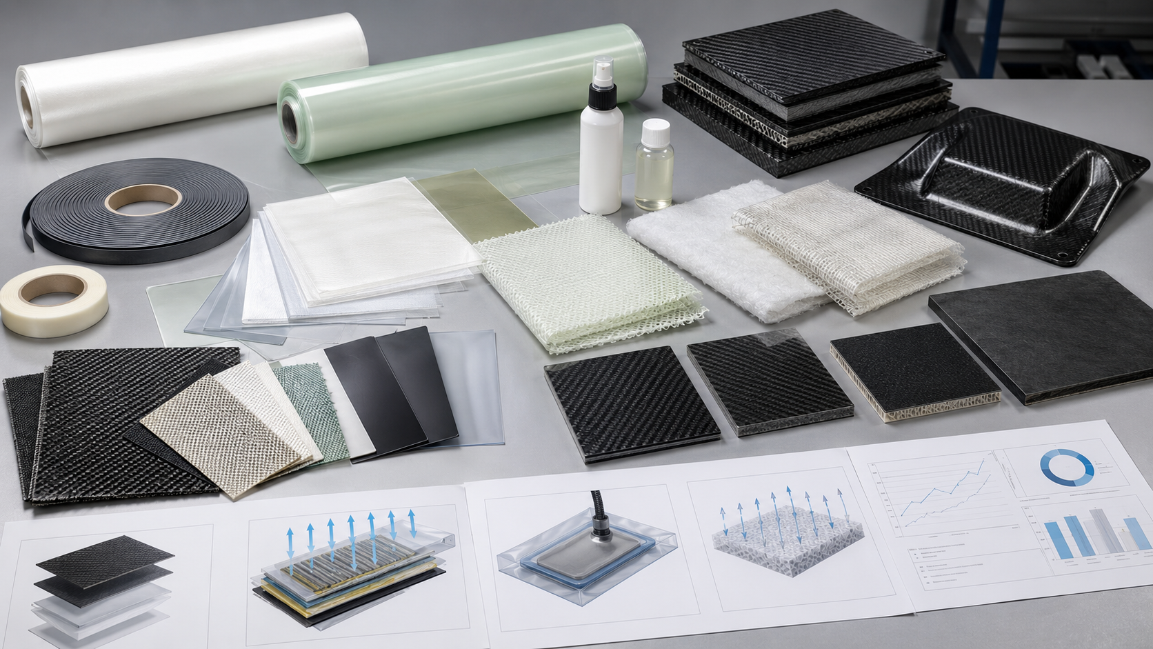
Auxiliary materials do not usually appear in the finished product, but they strongly affect manufacturing quality.
These materials help control resin flow, vacuum, release, surface texture, cure, and demolding.
Common auxiliary materials include:
|
Auxiliary Material |
Role in Production |
|---|---|
|
Peel ply |
Creates a controlled surface for bonding or secondary processing |
|
Release film |
Helps separate laminate from consumables or tooling |
|
Breather cloth |
Allows air and volatiles to move under vacuum |
|
Bleeder material |
Absorbs excess resin in some processes |
|
Vacuum bagging film |
Seals the laminate for vacuum consolidation |
|
Sealant tape |
Holds vacuum bag edges airtight |
|
Flow media |
Helps resin move during infusion |
|
Release agent |
Helps demold parts from tools |
|
Adhesive film |
Bonds skins, cores, inserts, or secondary structures |
|
Surface film |
Improves outer surface quality in some composite systems |
Buyers often focus only on carbon fiber grade, but auxiliary materials can affect:
-
Void content
-
Resin-rich areas
-
Surface defects
-
Bonding quality
-
Demolding damage
-
Cure consistency
-
Traceability
-
Repeatability
For example, poor vacuum bag integrity can cause voids. Incorrect peel ply can affect bonding. Poor release control can damage the surface. Wrong flow media layout can create dry spots or resin-rich zones during infusion.
Auxiliary materials are part of the production system.
They should be controlled through work instructions, process records, and supplier quality procedures, especially for repeat production or structural parts.
How Material Form Affects Process Route, Cost and Quality
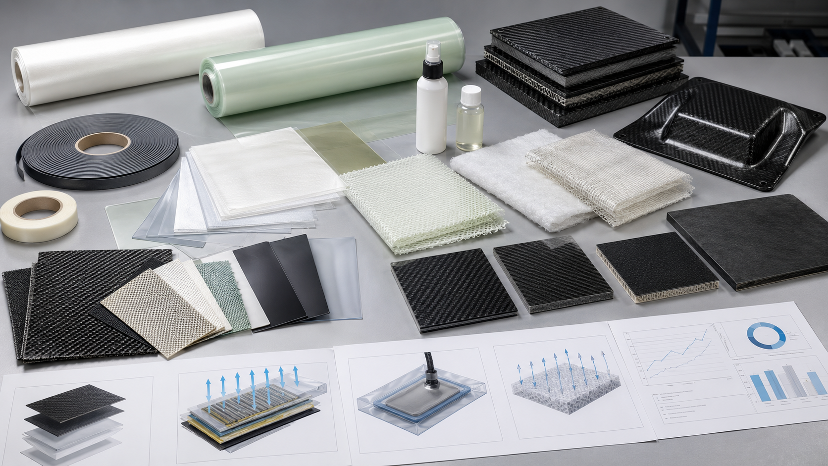
Material selection and process selection cannot be separated.
A material form that works well in one process may perform poorly in another.
|
Material Form |
Common Process Routes |
Main Advantage |
Main Constraint |
|---|---|---|---|
|
Raw tow |
Filament winding, pultrusion, weaving, braiding |
Low material cost and automation potential |
Requires process equipment and tension control |
|
Dry fabric |
Wet layup, vacuum infusion, RTM, VARTM |
Flexible, accessible, suitable for larger parts |
Resin control depends on process discipline |
|
Prepreg |
Autoclave, oven cure, press molding, ATL/AFP |
Controlled resin content and repeatability |
Cold storage, out-life, tooling, and cure control |
|
Core material |
Sandwich panel molding and bonding |
High stiffness-to-weight ratio |
Bonding, edge closure, insert design, and compatibility |
|
Auxiliary materials |
Vacuum bagging, infusion, cure, demolding |
Supports process quality |
Wrong selection can cause defects |
Process capability sets a hard ceiling on what the material can achieve.
Autoclave curing at around 0.6–0.7 MPa and 120–180°C can support high fiber volume fraction and low void content when the prepreg system and process are suitable.
Vacuum infusion often operates near −0.9 bar vacuum and needs resin viscosity low enough for complete wet-out. In many infusion systems, resin viscosity under 500 mPa·s is helpful for reliable flow, depending on part size and fabric architecture.
Hand layup is more accessible, but fiber volume fraction and void control are usually less consistent than well-controlled infusion, press molding, or autoclave prepreg processing.
Production volume also changes the decision:
|
Production Situation |
Practical Material Direction |
|---|---|
|
Prototype under 100 pieces |
Dry fabric, wet layup, simple infusion, or CNC-cut stock material |
|
Mid-volume 100–1,000 pieces |
Infusion, compression molding, prepreg where quality needs justify it |
|
High-volume 1,000+ pieces |
RTM, press molding, automated fiber placement, pultrusion, or winding |
|
High-precision structural part |
Prepreg, UD reinforcement, controlled cure, and strong inspection plan |
|
Large lightweight panel |
Dry fabric with core material or prepreg sandwich structure |
|
Continuous profile or tube |
Tow-based pultrusion or winding where geometry fits |
Surface quality also matters.
Visible carbon surfaces may need 2×2 twill, spread-tow fabric, in-mold coating, high-quality tooling, or controlled prepreg layup. Hidden structural surfaces may prioritize fiber orientation, thickness, bonding, and mechanical performance over cosmetic weave.
The right material choice is not the most expensive option.
It is the option that matches performance, process, quantity, surface class, quality control, and cost.
Carbon Fiber Materials Across Common Applications
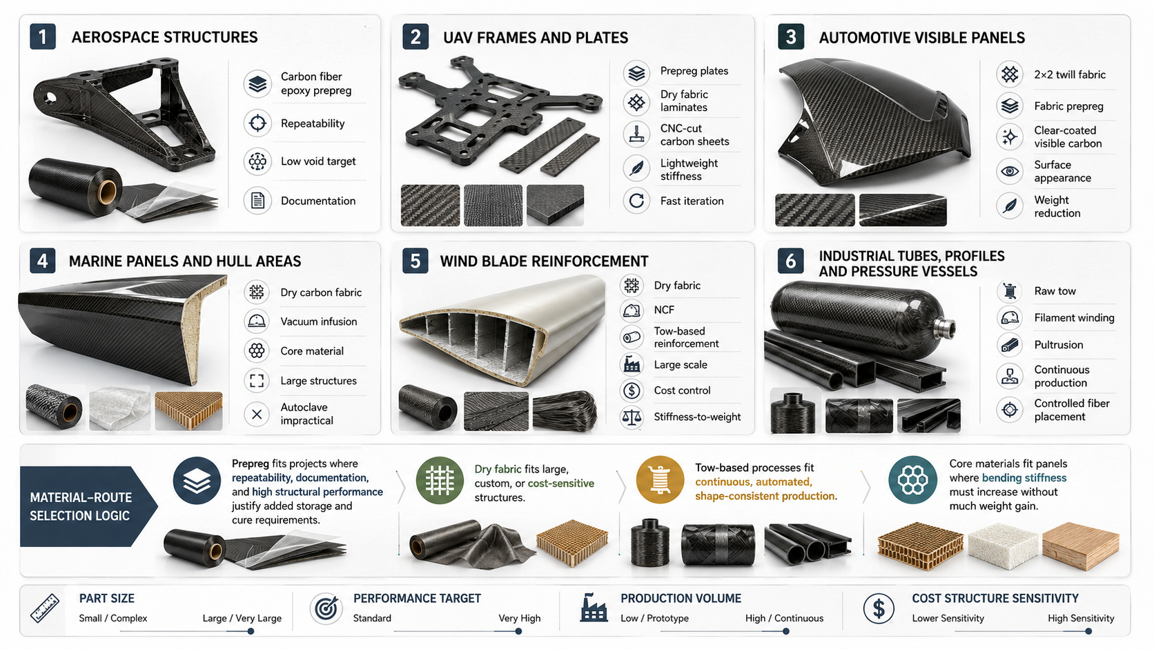
Different industries use different carbon fiber material systems because the part size, performance target, production volume, and cost structure are different.
|
Application |
Common Material System |
Why It Fits |
|---|---|---|
|
Aerospace structures |
Carbon fiber epoxy prepreg, often UD and fabric prepreg |
High repeatability, low void targets, strong documentation path |
|
UAV frames and plates |
Prepreg plates, dry fabric laminates, CNC-cut carbon sheets |
Lightweight stiffness, fast iteration, controlled thickness |
|
Automotive visible panels |
2×2 twill fabric, fabric prepreg, clear-coated visible carbon |
Surface appearance and weight reduction |
|
Marine panels and hull areas |
Dry carbon fabric with vacuum infusion and core material |
Large structures where autoclave processing is impractical |
|
Wind blade reinforcement |
Dry fabric, NCF, tow-based reinforcement |
Large scale, cost control, stiffness-to-weight improvement |
|
Industrial tubes and profiles |
Raw tow in filament winding or pultrusion |
Continuous production and efficient fiber placement |
|
Pressure vessels |
Carbon tow with controlled winding angle and resin system |
High hoop strength and repeatable automated production |
|
Sports equipment |
Prepreg, woven fabric, local UD reinforcement |
Tuned stiffness, low weight, controlled flex |
|
Medical imaging panels |
Carbon fiber skins with core material |
Radiolucency, stiffness, low weight, flatness |
|
Robotics components |
Prepreg plate, CNC-cut carbon sheet, molded carbon parts |
Stiffness-to-weight ratio and repeatable geometry |
The pattern is consistent.
Prepreg fits projects where repeatability, documentation, and high structural performance justify the added storage and cure requirements.
Dry fabric fits large, custom, or cost-sensitive structures where infusion or wet layup is practical.
Tow-based processes fit continuous, automated, shape-consistent production.
Core materials fit panels where bending stiffness must increase without much weight gain.
Auxiliary materials support production quality across all of these routes.
How Buyers Should Choose the Right Carbon Fiber Material
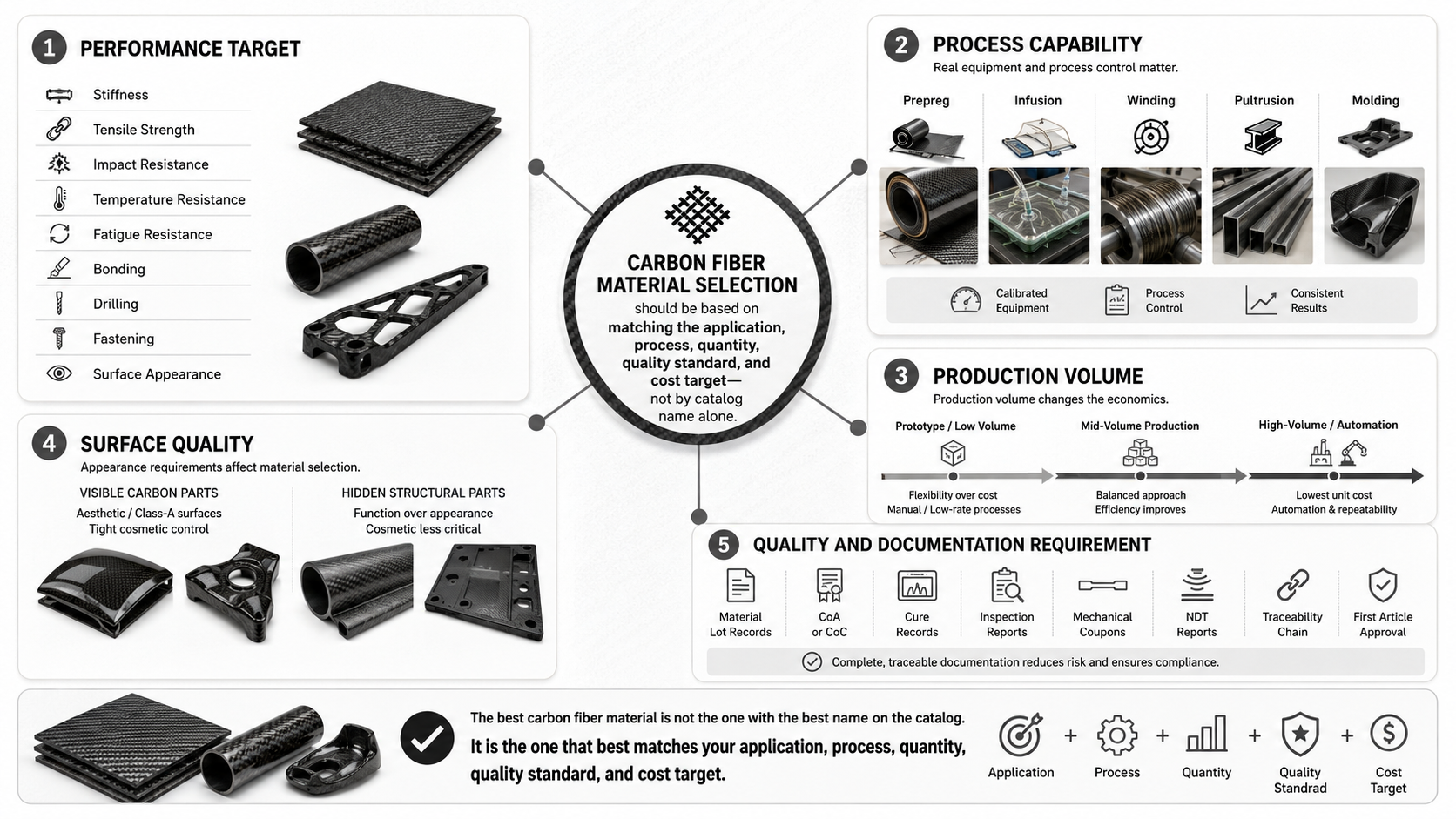
A buyer should not choose carbon fiber material by name alone.
The correct selection comes from five decision dimensions:
-
Performance target
-
Process capability
-
Production volume
-
Surface quality
-
Quality and documentation requirement
1. Performance Target
Define what the part must do.
Ask:
-
Is stiffness the main goal?
-
Is tensile strength the main goal?
-
Is impact resistance important?
-
Is the part exposed to heat?
-
Does it need fatigue resistance?
-
Will it be bonded, drilled, or fastened?
-
Is surface appearance functional or cosmetic?
High stiffness may push the design toward UD prepreg or high-modulus reinforcement.
Impact resistance may require woven fabric, toughened resin, hybrid fabric, or local reinforcement.
Temperature resistance may require a resin system with Tg at least 20–30°C above service temperature.
2. Process Capability
Match material to the manufacturing process available.
A supplier with autoclave curing, controlled prepreg storage, and batch records can support prepreg projects better than a shop without cold-chain control.
A supplier with strong infusion experience may be the better route for large dry-fabric structures.
A supplier with filament winding or pultrusion equipment may be the correct choice for tubes, vessels, and continuous profiles.
The material should fit the factory’s real process capability.
Not the other way around.
3. Production Volume
Quantity changes the economics.
For one-off prototypes, simple tooling and accessible materials may matter more than maximum laminate performance.
For mid-volume production, repeatability and controlled process time become more important.
For high-volume parts, automation, cycle time, material yield, and process stability can dominate the decision.
4. Surface Quality
Visible carbon parts require different material choices than hidden structural parts.
A visible automotive trim panel may need twill fabric, spread-tow fabric, clear coating, surface film, or high-quality tooling.
A hidden bracket may need UD reinforcement, thickness control, hole quality, and mechanical testing more than perfect weave appearance.
Surface class should be defined before material selection is finalized.
5. Quality and Documentation
Some projects need only basic dimensional and visual inspection.
Others require:
-
Material lot records
-
CoA or CoC
-
Cure records
-
Inspection reports
-
Mechanical coupons
-
NDT reports
-
Traceability chain
-
First article approval
More quality evidence usually changes material and process selection.
If traceability, repeatability, and inspection records are important, this should be included before quotation.
A simple buyer decision table can help:
|
Buyer Situation |
Better Starting Point |
|---|---|
|
Need high repeatability and low voids |
Prepreg with controlled cure |
|
Need large part size and lower tooling cost |
Dry fabric with infusion |
|
Need continuous tube or profile |
Tow-based winding or pultrusion |
|
Need visible carbon surface |
Twill fabric, spread-tow, or fabric prepreg |
|
Need lightweight panel stiffness |
Carbon skins with core material |
|
Need temperature resistance |
Resin system review before material approval |
|
Need production evidence |
Material traceability and quality-control plan |
The best carbon fiber material is not chosen from a catalog alone.
It is chosen by matching the application, process, quantity, quality standard, and cost target.
What to Send HyperX Carbon for Material and Process Review
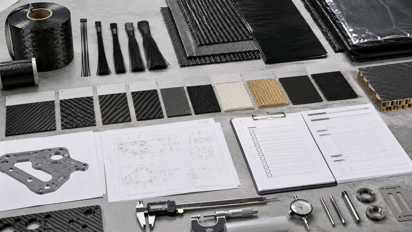
A strong carbon fiber material decision starts with clear project input.
Before requesting a quote, send:
-
3D CAD file
-
2D drawing
-
Part size
-
Part thickness target
-
Quantity target
-
Application
-
Load direction
-
Surface requirement
-
Weight target
-
Temperature environment
-
Chemical or moisture exposure
-
Tolerance requirement
-
Visible or hidden surface class
-
Preferred material, if any
-
Required production method, if any
-
Inspection requirement
-
Documentation requirement
-
Timeline
For material-specific review, also send:
-
Whether you want finished parts or material supply
-
Whether prepreg, dry fabric, tow, or core material is preferred
-
Whether your team has in-house manufacturing capability
-
Whether cold storage is available for prepreg
-
Whether resin selection is already defined
-
Whether traceability records are required
-
Whether first article approval is required
At HyperX Carbon, we review material selection together with the production route.
For custom carbon fiber parts, this may include prepreg layup, molding, CNC cutting, trimming, surface finishing, inspection, and packing. For material-related projects, it may include fiber grade, fabric style, prepreg type, resin system, core selection, storage requirements, and process compatibility.
If you are not sure whether to buy carbon fiber materials or finished carbon fiber parts, send your application and production plan for review.
We can help evaluate the material route before production begins.
The best composite structures are not only manufactured correctly.
They are specified correctly from the start.