Carbon fiber is one of the most unforgiving materials you can run on a CNC machine.
It is also one of the most rewarding when the process is done correctly.
The same properties that make CFRP valuable in aerospace, motorsport, UAVs, robotics and high-performance engineering also make it difficult to machine:
-
Extreme fiber hardness
-
Layered laminate structure
-
Abrasive carbon reinforcement
-
Heat-sensitive resin matrix
-
Fine conductive dust
-
Directional fiber behavior
Get the process wrong, and the result can be delamination, frayed edges, blown-out drill exits, poor hole quality, heat-damaged resin, inconsistent dimensions and conductive dust that damages machines.
Get it right, and carbon fiber CNC machining can deliver clean, tight-tolerance parts with accurate holes, sharp profiles, controlled edges and stable repeatability.
This guide explains what buyers and engineering teams should understand before sending a carbon fiber CNC machining RFQ.
At HyperX Carbon, CNC machining review starts with material thickness, laminate type, hole requirements, edge quality, tolerance, surface requirement, quantity and final application. Those inputs decide the tooling, toolpath, fixturing, dust control and inspection route before the spindle turns.
Carbon Fiber CNC Machining: What This Guide Covers

Carbon fiber CNC machining is not simply metal machining with different speeds and feeds.
It is a separate process built around fiber shear, laminate support, heat control, dust extraction and edge-quality inspection.
This guide covers:
-
Tooling selection for CFRP machining
-
CNC cutting speeds, feeds and pass strategy
-
Carbon fiber drilling and exit-side delamination control
-
Trimming allowance and clean edge production
-
Post-machining sanding, deburring and edge sealing
-
Carbon fiber dust hazards and machine protection
-
3-axis, 4-axis and 5-axis CNC selection
-
CNC machining vs. waterjet cutting
-
Industry tolerance expectations
-
What buyers should send before quotation
A common working baseline for carbon fiber CNC machining includes:
|
CNC Variable |
Practical Baseline |
|---|---|
|
Spindle speed |
18,000–30,000 RPM |
|
Feed rate |
1,000–1,500 mm/min |
|
Depth of cut |
1.5–2 mm per pass, depending on thickness and tool diameter |
|
Pass strategy |
Shallow passes, not one aggressive plunge |
|
Critical edges |
At least two passes, including a light finishing pass |
These are not random settings.
They are the kind of process decisions that separate clean CFRP parts from rejected ones.
Every strong carbon fiber CNC machining process comes down to the same core decisions:
-
Sheet thickness and tolerance — define them before toolpathing, not after.
-
Composite-rated tooling — PCD, CVD diamond-coated carbide or compression tools, not generic metal-cutting end mills.
-
Pass strategy — shallow roughing, controlled semi-finish, final light finishing.
-
Workholding — vacuum tables, backing support and rigid fixturing reduce movement-related edge damage.
-
Dust control — HEPA extraction, ventilation and PPE are part of the machining system, not optional accessories.
-
Inspection method — hole quality, edge fray, delamination and dimensional reports should be defined before production.
For RFQ review, buyers should send CAD or DXF files, 2D drawings, hole tolerances, edge requirements, material thickness, laminate type, surface requirement and quantity before asking for a machining quote.
What Makes Carbon Fiber CNC Machining Different from Conventional Machining
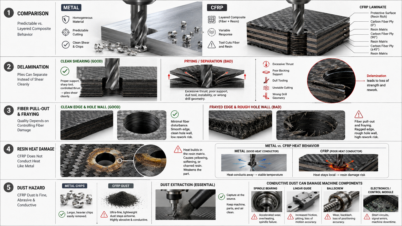
Steel and aluminum behave in predictable ways under a cutting tool.
Carbon fiber does not.
CFRP is a layered composite made from stiff carbon fibers bonded inside a resin matrix. The tool is not cutting through one uniform material. It moves through high-modulus fibers and a softer resin system, sometimes within the same pass.
That is where machining risk begins.
Delamination
Delamination happens when the tool stops shearing the laminate cleanly and starts prying the layers apart.
Common causes include:
-
Feed rate too high
-
Excessive thrust force
-
Poor backing support
-
Dull tooling
-
Aggressive plunge strategy
-
Weak fixturing
-
Incorrect drill geometry
For aerospace, motorsport, UAV or high-performance structural parts, delamination can be an automatic reject.
A carbon fiber part can look close to shape and still be structurally unacceptable if laminate layers separate during machining.
Fiber Pull-Out and Fraying
If tool geometry is wrong, carbon fibers do not get cut cleanly.
They get dragged out.
The result is:
-
Ragged edge quality
-
Rough hole walls
-
Local fiber damage
-
Reduced strength near interfaces
-
Poor cosmetic finish
-
Higher rework risk
Frayed edges are not only cosmetic. They can indicate tool wear, wrong cutting direction, unstable workholding or excessive machining force.
Resin Heat Damage
CFRP does not carry heat away like metal.
Cutting heat can build quickly at the tool-workpiece interface.
Above about 150–200°C, the resin matrix can soften, yellow, scorch or break down. You may see discoloration, glassy residue or darkened hole walls.
But the more serious issue may be hidden: interlaminar shear strength can be affected before the damage looks severe on the surface.
Carbon Fiber Dust
Carbon fiber does not make metal chips.
It produces fine, abrasive and conductive dust.
That dust can:
-
Enter spindle bearings
-
Damage linear guides
-
Contaminate ballscrews
-
Short out electrical systems
-
Settle inside servo drives and terminal strips
-
Create operator exposure concerns
-
Affect surface cleanliness before coating or bonding
Carbon fiber CNC machining requires purpose-built tooling, controlled parameters and extraction systems that treat dust as a real process and safety hazard.
A shop that machines CFRP like aluminum is not running a controlled carbon fiber machining process.
Tooling Selection for Carbon Fiber CNC Machining: PCD, Carbide and Compression Bits
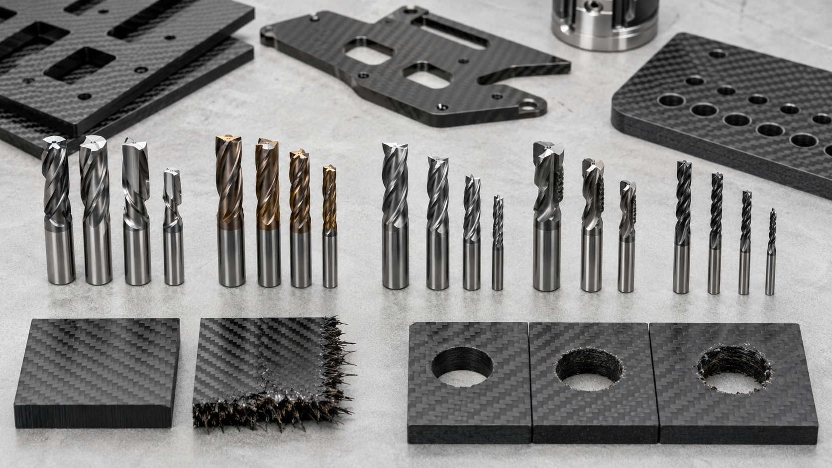
Tool choice is where many CFRP jobs are won or lost before the spindle even turns.
The wrong tool does not only shorten tool life.
It can destroy edge quality, increase delamination and create hole-wall damage that cannot be repaired later.
Three tool families dominate carbon fiber CNC machining:
-
PCD tools
-
CVD diamond-coated carbide tools
-
Compression-geometry routers
Each has a different role.
PCD vs. CVD Diamond-Coated Carbide vs. Standard Carbide
|
Tool Type |
Hardness, HV |
Life vs. Carbide |
Re-sharpenable |
|---|---|---|---|
|
Standard carbide |
~1,800–2,200 |
Baseline |
Yes |
|
CVD diamond-coated carbide |
~8,500 |
10–50×, up to 100× |
No |
|
PCD |
~6,000 |
10–20× |
Yes |
CVD diamond is extremely hard — about 3–4× harder than carbide and harder than PCD.
In stable, low-impact trimming operations, CVD-coated tools can last 3–4× longer than PCD at the same conditions.
But harder does not mean better for every CFRP job.
PCD has a cobalt binder that gives it higher toughness. Under vibration, interrupted cuts or imperfect fixturing — conditions that often happen in real production — PCD is more predictable. CVD edges may chip or peel from the base material.
Once a CVD coating wears through to bare carbide, tool degradation accelerates quickly.
For hole quality, PCD often performs better than CVD-coated drills in CFRP with higher resin content because it holds a sharp cutting edge longer and produces cleaner hole walls.
For well-fixtured trimming in repeat production, a PCD router can rough and finish near net shape with strong repeatability.
PCD tools may cost 3–5× more than carbide upfront. But with 10–20× tool life and re-sharpening potential, cost per accepted part can run 30–70% lower than carbide at the same throughput.
For repeat production, tool cost should be judged by cost per accepted part — not purchase price.
Compression Bits: Solving the Two-Surface Problem
Standard up-cut routers pull fibers upward.
The top face may stay cleaner, but the bottom face tears.
A down-cut tool flips the problem. The bottom face improves, but the top surface can suffer.
Compression bits combine both geometries:
-
Up-cut helix on the lower portion
-
Down-cut helix above
-
Cutting forces meet around the laminate mid-plane
-
Both faces are compressed inward
The result is significant:
-
Top and bottom fraying can drop by 50–80% compared with single-direction carbide tools in FRP routing.
-
With CVD diamond coating and solid workholding, edge fray width on CFRP panels can hold to <0.1–0.2 mm.
-
Conventional two-flute up-cut carbide at comparable feeds and speeds may produce 0.3–0.5+ mm fray width.
Compression geometry is the right call when both faces carry appearance, assembly or tolerance requirements.
This matters for aerospace skins, structural panels, UAV frames and visible carbon fiber profiles.
Geometry and Coating by Operation
For cutting and profiling, use a 2-flute PCD or CVD diamond-coated carbide router.
Keep helix angle low — about 10–20° — to reduce axial fiber pull-out.
Four-flute tools can pack dust and accelerate coating failure in CFRP.
For side-cutting passes, radial depth of cut should stay at or below ¼ tool diameter.
For drilling, use PCD drills or CVD diamond-coated carbide drills. A point angle of 130–140° helps reduce thrust and delamination at entry and exit. Split-point or brad-point geometries can reduce the delamination factor further, especially in aerospace work where the specification ceiling may sit at Fd < 1.1.
For edge trimming, a 2-flute, low-helix PCD router is preferred for well-fixtured parts.
A corner-radius or ball-end tool can extend tool life during roughing, followed by a square-end tool with minimal depth of cut for final sizing.
Tool Change Indicators
Do not wait for visible part failure.
In carbon fiber machining, a worn tool can create bad parts before the damage becomes obvious.
Change the tool when you see:
-
Rising spindle load at the same feed and speed
-
More fuzz or fiber pull-out on edges
-
More breakout on hole exits
-
Visible chipping under magnification
-
Hole diameter growth beyond 0.02–0.03 mm over nominal
-
Any delamination factor exceeding customer specification
For CVD-coated tools, stop using the tool once diamond coating wears through to bare carbide on the cutting edge.
At that point, the tool stops cutting cleanly and starts pulling fibers.
CNC Cutting Carbon Fiber: Speeds, Feeds and Pass Strategy

Carbon fiber does not cut like metal.
It does not form chips.
It does not absorb heat.
It shatters, frays and delaminates when the tool starts prying instead of shearing.
The entire speed-feed-depth strategy has one job:
Keep the tool shearing sharp and clean.
A practical baseline is:
|
Parameter |
Working Range |
|---|---|
|
Spindle speed |
18,000–25,000 RPM |
|
Feed rate |
1,000–1,500 mm/min |
|
Depth of cut |
0.5×D per pass, maximum 1×D |
|
Chip load target |
0.05–0.08 mm/tooth |
|
Final stock allowance |
0.1–0.2 mm |
These settings follow a clear logic:
-
High surface speed creates clean fiber shear.
-
Low chip load reduces fiber pull-out and resin heat damage.
-
Shallow passes reduce lateral force that peels laminate layers apart.
-
A final light pass removes fuzz and stabilizes dimensions.
Why Metal Parameters Fail on CFRP
Metal machining can use moderate RPM, heavier chip loads and deeper cuts because metal is ductile.
It deforms, flows and carries heat away from the cut zone.
CFRP does not.
CFRP is anisotropic, abrasive and brittle. Push a large chip load through carbon fiber and you get delamination, frayed edges and resin scorching.
High spindle speed keeps the cutting edge in the shearing zone. Lower feed rate keeps chip load small enough that fibers are cut, not pulled.
The goal is not maximum material removal. The goal is controlled fiber separation without laminate damage.
Depth Strategy by Material Thickness
Depth of cut should scale with material thickness and tool diameter.
|
Plate Thickness |
Recommended DOC |
Pass Strategy |
|---|---|---|
|
0.5–1 mm |
0.3–0.5 mm |
2–3 passes + finish |
|
1–3 mm |
0.5–1.0 mm, about 0.5×D |
2–3 passes |
|
3–10 mm |
1.5–2.0 mm, ≤0.5×D |
4–6 passes |
|
10+ mm |
≤0.5×D strict |
5–7+ passes |
One rule applies at every thickness:
Leave 0.1–0.2 mm for a final light finishing pass.
That last pass cleans the wall, removes fuzz and brings the dimension into tolerance. Skip it, and roughing damage remains in the finished edge.
Climb vs. Conventional Milling
Cut direction matters more in CFRP than in many metals.
Climb milling pushes cutting forces toward the already-machined surface, reducing exit-side fraying. For thin sheets under 2 mm with a single-flute burr, climb milling at reduced feed and depth of cut often produces cleaner profiles.
For thicker stock — 4 mm and above — use compression geometry. It climbs on the bottom half and cuts in the opposite direction on the top, compressing both faces inward.
Another adjustment matters:
Reduce feed by 30–40% on toolpath segments where the cut runs parallel to the dominant fiber direction.
Fibers aligned with the cut direction are pull-out risks. Slower feed gives the tool time to shear instead of drag.
Carbon Fiber Drilling: Preventing Delamination and Fiber Breakout
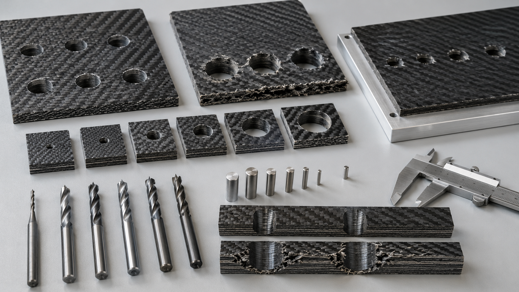
Drilling CFRP comes down to one thing:
thrust force.
Everything else — drill geometry, feed rate, backing and fixturing — exists to keep thrust below the laminate’s critical threshold before the bottom plies peel apart.
As the drill approaches the exit face, the remaining uncut thickness decreases. The last plies have no material underneath to support them. Thrust bends them outward. At a certain load, interlaminar cracking begins.
Exit delamination is usually worse than entry damage because the material underneath has not yet been cut. It gets pushed, not sheared.
Delamination Factor
Researchers measure drilling damage with the delamination factor:
Fd = Dmax / D0
Where:
-
Dmax = maximum damaged diameter
-
D0 = nominal drilled diameter
In aerospace structural work, anything above 1.1 can trigger rejection.
Standard twist drills with 118° point angles can hit 1.3–1.4 regularly.
That is not a small process variable.
It is the difference between a conforming part and scrap.
Control Feed Rate First
Feed rate causes more drilling damage than almost any other single parameter.
Cutting feed in half can reduce delamination extension by 20–50%, depending on geometry and laminate.
Raising feed from 0.05 mm/rev to 0.20 mm/rev can push delamination factor from around 1.05–1.10 to 1.20–1.30 at constant cutting speed.
Practical feed guidance:
|
Drill Size / Tool Type |
Recommended Feed |
|---|---|
|
Ø4–6 mm PCD or CVD diamond-coated drills |
0.02–0.06 mm/rev |
|
Exit-integrity-critical holes |
Do not exceed 0.10 mm/rev |
|
Ø3 mm small-diameter tools |
0.01–0.03 mm/rev |
If the hole matters for assembly or structure, feed control is not optional.
Drill Geometry Changes the Outcome
Geometry selection sets the delamination threshold before the job starts.
Step drills split cutting into staged diameter regions. This spreads thrust across multiple engagement zones.
Compared with standard twist drills, step drills can reduce average damage extension by 30–40% and bring delamination factors down to 1.05–1.10.
Elliptical and bullet-point composite drills lower local thrust at the chisel region. They cut through the last plies rather than pushing through them.
Composite-specific point angles of 85–100°, compared with 118°+ on metal drills, can make a measurable difference.
For larger final diameters, use a pilot hole strategy:
-
Drill Ø2–3 mm first.
-
Step to an intermediate size.
-
Finish to nominal diameter.
Each pass removes less radial material. Thrust stays lower. Exit spalling drops.
Backing, Fixturing and the Exit Face
No parameter adjustment can fix poor fixturing.
Rigid clamping on both faces matters.
So does a backing plate under the drill exit.
Backing materials may include:
-
MDF
-
Aluminum
-
Composite support plate
In laminates thinner than 3 mm, backing is not optional.
Another detail matters: reduce feed through the last 0.5–1.0 mm of thickness. That is where bending stress peaks. A slow, steady feed through the exit zone helps prevent the sudden load spike that causes fiber breakout.
A clean outside profile means little if the holes cannot assemble correctly.
Hole quality is a structural and assembly requirement, not only a machining detail.
Carbon Fiber Trimming and Edge Quality: Clean, Fray-Free Profiles
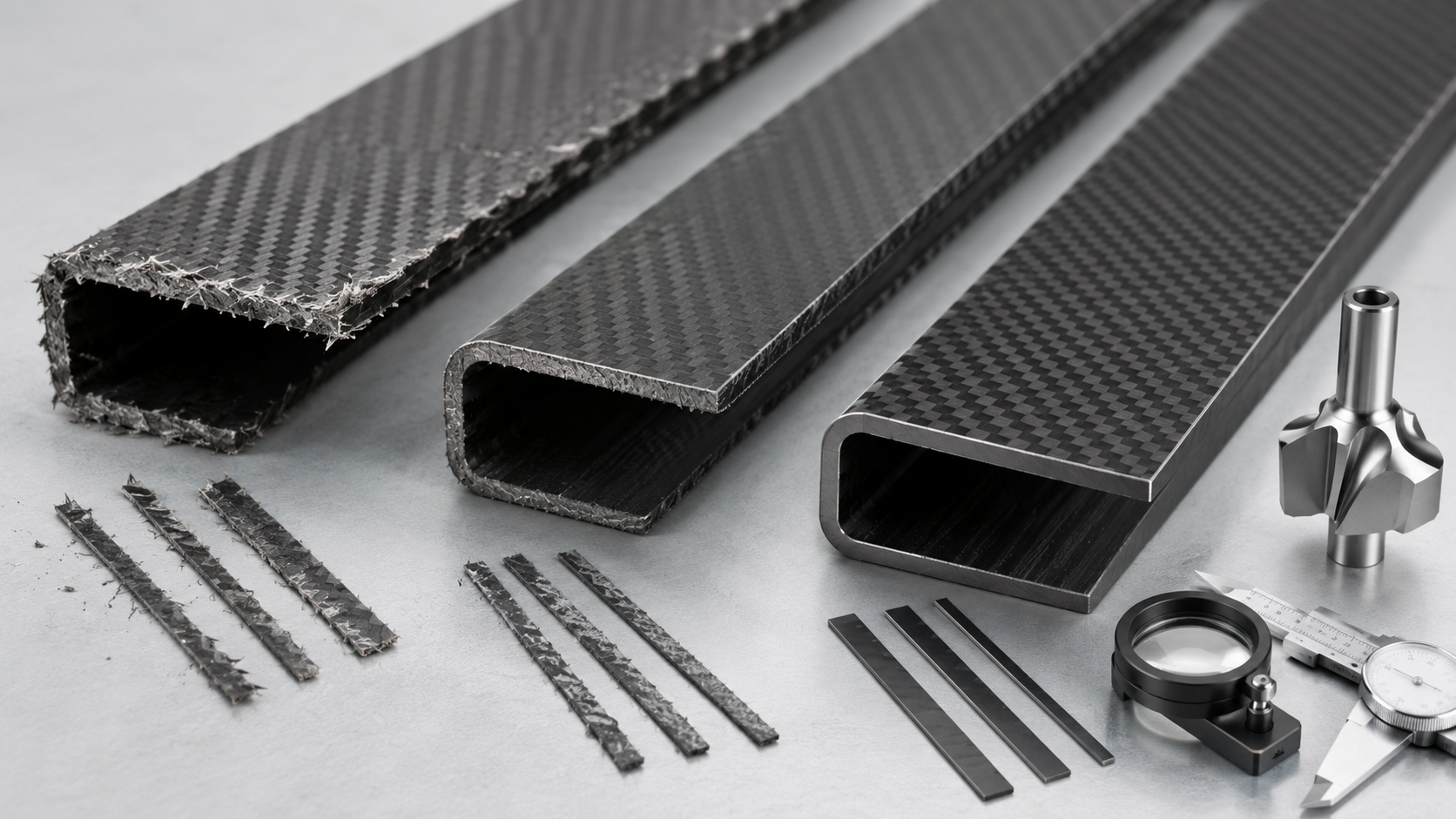
Edge quality in carbon fiber is not only cosmetic.
A frayed profile or delaminated edge on a structural part is not something to sand down and ship. It can be a rejection, and in aerospace, motorsport, UAV or industrial load-bearing applications, it can become a liability.
The trimming stage decides that outcome.
Trimming Allowance: How Much to Leave
Most carbon fiber workflows use a three-step sequence:
Rough cut → leave trimming stock → CNC finish trim
Standard trimming stock allowance is 0.3–1.0 mm per side.
On complex 3D contours or parts with springback risk, increase that to 1.5 mm per side.
That margin exists for a reason.
Rough cutting — especially waterjet or laser — can leave heat-affected zones, resin scorching, micro-delamination or surface fiber damage. The finish trim must remove that damage and account for fixturing deflection.
For zero-delamination requirements, the rule is direct:
Leave at least the maximum contour error of the previous operation, plus 0.1 mm.
Compression Routers vs. Single-Direction Tooling
On laminates ≥4 mm thick, tool geometry decides which face pays the price.
An up-cut router pulls clean on top and tears the bottom.
A down-cut router flips the problem.
A compression router uses opposite helices: up-cut on the lower flute section and down-cut above. Both faces are compressed inward at the mid-plane.
|
Tool Type |
Top Surface Fray |
Bottom Surface Fray |
|---|---|---|
|
Single up-cut |
0.4–0.6 mm |
0.1–0.3 mm |
|
Single down-cut |
0.5–0.8 mm |
Better |
|
Compression router |
0–0.2 mm |
0–0.2 mm |
In batch production on autoclave-cured structural laminates, compression tooling can drop defect rates from 3–5% to under 1%.
That means less rework, less scrap and more predictable delivery.
Light Finishing Passes
Rough-then-finish is not optional.
It is the path to Grade 0 edge quality — zero visible delamination and interlaminar crack length under 0.05 mm.
A working pass structure:
|
Pass |
Typical Parameters |
|---|---|
|
Rough pass |
DOC 0.5–1.5 mm; feed 2–6 m/min; fz 0.02–0.05 mm/tooth |
|
Semi-finish |
Bring to 0.15–0.25 mm from final contour; reduce feed 30–50%; fz 0.015–0.03 mm/tooth |
|
Finish pass |
DOC 0.05–0.15 mm; feed 1–3 m/min; fz 0.01–0.02 mm/tooth |
For surfaces requiring Ra ≤3.2 µm and Grade 0 edge quality, run two finish passes:
-
First finish pass: 0.10–0.15 mm
-
Final pass: 0.05–0.08 mm
Repeat the final pass along the same toolpath to shear remaining fiber stubs.
For 0.8 mm total stock, a practical allocation is:
0.5 mm rough → 0.2 mm semi-finish → 0.1 mm finish, split 0.06 + 0.04 mm
This sequence delivers stable Grade 0–1 edge quality on most 5–10 mm carbon fiber plate.
One hard boundary:
Do not let the final pass drop below 0.05 mm DOC.
Below that threshold, the tool may stop cutting and start rubbing. That creates high-density micro-fraying — the exact problem the finishing stage is supposed to remove.
Post-Machining Edge Finishing: Sanding, Deburring and Edge Sealing
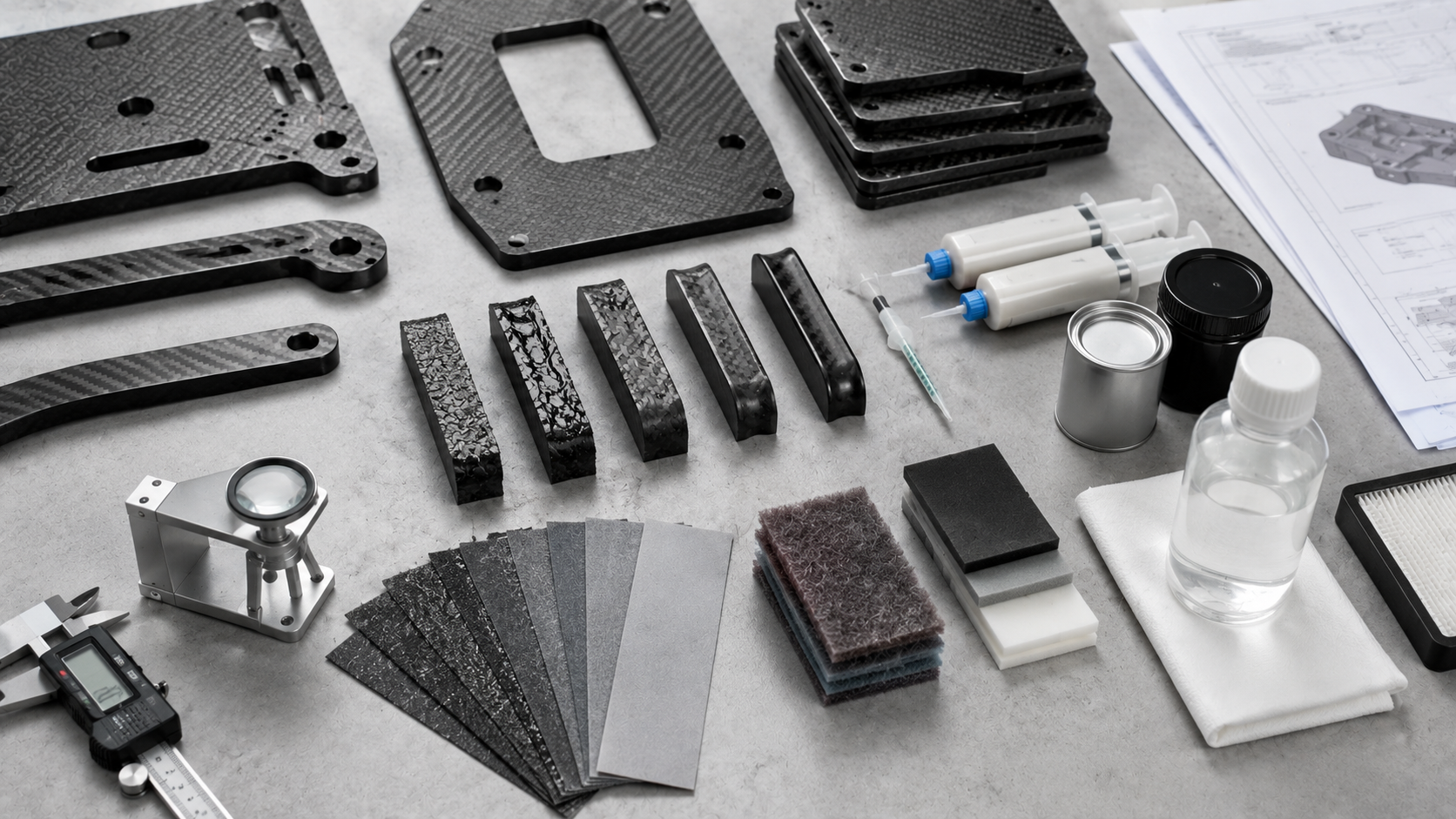
When the CNC program finishes, the spindle stops.
At that moment, you may have a machined part — but not always a finished part.
Edges still need attention. The correct finishing method depends on volume, geometry and what happens to the part next.
Hand Sanding vs. Mechanical Deburring
Hand sanding is the right choice for:
-
Small runs
-
Complex profiles
-
Internal corners
-
Surfaces close to cosmetic faces
-
Edges needing a controlled 0.1–0.3 mm break
-
Spot repairs
-
Pre-coating touch-up
Mechanical deburring — belt sanders, brush rollers or vibratory finishing — makes more sense when:
-
Volume is high
-
Consistency matters more than flexibility
-
Edge rounding needs repeatability
-
Coating preparation must follow a controlled workflow
Post-machining finishing can change cost, lead time and long-term durability. It should be defined before quotation.
Grit Sequence for Carbon Fiber Edges
Do not skip grits.
Each pass should remove at least 80–90% of the scratch depth left by the previous grade. Residual coarse scratches show up under topcoat and can worsen under stress.
|
Grit |
Purpose |
|---|---|
|
P80–P120 |
Remove tool marks, large burrs and rough geometry |
|
P180–P240 |
Remove P120 scratches and approach final dimensions |
|
P320–P400 |
Pre-coat finish for structural bonding or primer |
|
P600–P800 |
Visible edges on appearance parts |
For coating adhesion, target Ra 1.0–3.2 µm before primer.
Coatings over Ra below 0.8 µm can lose mechanical grip.
Above 3.2 µm, film continuity can break down.
IPA Cleaning Before Coating or Bonding
After the final sand pass, vacuum the surface first.
Then wipe with 99% IPA and a lint-free cloth.
Use the two-cloth method:
-
The first cloth wet-wipes in one direction.
-
The second cloth follows immediately to lift residue and solvent.
Do not let IPA pool on the surface.
Allow it to evaporate before adhesive or primer.
For structural bonding, apply adhesive within 30–120 minutes of cleaning.
For spray coating, prime within 2–4 hours.
Past that window, re-wipe or lightly re-sand to remove settled carbon dust.
Cleaning is part of the machining quality system, not a cosmetic afterthought.
Edge Sealing for Long-Term Durability
Exposed fiber ends can absorb moisture.
Over time, moisture can soften the resin matrix, weaken fiber-matrix adhesion and start edge delamination, especially under thermal cycling.
Edge sealants help stop that process.
Common options include:
-
Low-viscosity epoxy sealant — best chemical match for epoxy-matrix CFRP. Brush or spray 1–2 coats at 50–100 µm per pass, up to 0.3–0.5 mm total on exposed edges.
-
Polyurethane coating — useful when flexibility and impact resistance matter, such as automotive exterior parts.
-
UV-cure acrylic — useful for fast turnaround on small precision parts.
A practical sequence is:
Sand to P320–P400 → vacuum → blow dry → IPA wipe → apply sealant → cure → light sand if needed → final assembly or topcoat
For critical structural parts, run a post-seal edge soak test or microscopic inspection to confirm full coverage before the part moves forward.
Carbon Fiber Dust Hazards: Safety Protocols and Machine Protection

Carbon fiber dust does not announce itself.
It settles on terminal strips, creeps into servo drives and builds up inside electrical enclosures. Eventually, something shorts out.
There are three major hazard categories.
Inhalation
Most carbon fibers measure 7–8 µm in diameter, which is non-respirable by WHO definition.
But high-speed cutting and grinding can generate finer particles.
Exposure benchmarks include:
-
OSHA PEL: 5 mg/m³ for respirable fraction
-
ACGIH TLV: 3 mg/m³
-
U.S. Navy working guideline: 3 fibers/cm³
Even when fibers are not all respirable, dust should be controlled because machining produces mixed fiber, resin and fine particulate contamination.
Electrical Conductivity
Carbon dust is conductive.
It can bridge relay terminals, build up on PCBs and form low-resistance paths between components. Moisture makes this worse.
A professional setup should rate electrical enclosures at IP55 minimum.
Never blow down electrical cabinets with compressed air.
Use a HEPA vacuum instead.
Abrasion
Carbon fiber dust attacks linear guides, bearings and ballscrews slowly, constantly and quietly.
Practical responses include:
-
Negative-pressure enclosures
-
Dust extraction near the cutting zone
-
Telescoping steel covers with double-lip seals
-
Shortened lubrication intervals
-
Protected guideways
-
Sealed electrical cabinets
-
No compressed-air blowdown into electronics
Extraction and PPE Minimums
Standard industrial filtration such as MERV 8–13 captures large fibers well.
Fine graphite and resin particles below 5 µm can slip through.
Use a three-stage system:
Coarse pre-filter → mid-efficiency filter → HEPA terminal filter at 99.97% for 0.3 µm
Maintain ≥0.5 m/s face velocity at capture hoods.
Keep machining cavities at −50 to −100 Pa relative to the shop floor.
Minimum operator controls include:
-
N95 minimum during cutting
-
Half-mask with P100 cartridges for extended grinding
-
Nitrile gloves
-
Safety glasses with side shields
-
No dry sweeping — ever
Buyers should ask whether a supplier has enclosed machining, dust extraction, machine protection and operator safety procedures.
Dust control affects machine life, cutting consistency, part cleanliness and supplier credibility.
3-Axis vs. 4-Axis vs. 5-Axis CNC Machining for Carbon Fiber Parts
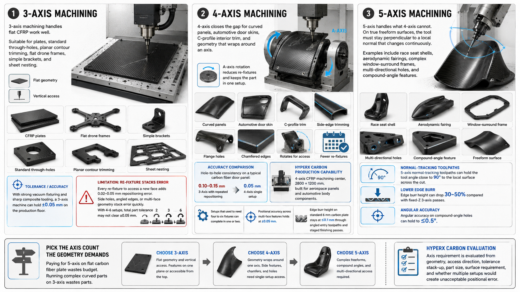
Axis count is not a spec to impress buyers.
It is a statement about what the machine can reach in one setup.
The correct axis count depends on part geometry, tolerance, access and budget.
3-Axis CNC Machining
3-axis machining handles flat CFRP work well.
It is suitable for:
-
Plates
-
Standard through-holes
-
Planar contour trimming
-
Flat drone frames
-
Simple brackets
-
Sheet nesting
With strong vacuum fixturing and sharp composite tooling, a 3-axis machine can hold ±0.05 mm on the production floor.
But every re-fixture to access a new face adds 0.02–0.05 mm of repositioning error.
Parts with side holes, angled edges or multi-face geometry stack that error quickly.
With 4–6 setups, total part tolerance may not clear ±0.05 mm.
4-Axis CNC Machining
4-axis machining closes that gap for curved panels, automotive door skins, C-profile interior trim and geometry that wraps around an axis.
Add A-axis rotation, and the part can be trimmed, drilled or chamfered without repeated flipping.
Side-edge trimming, flange holes and chamfers along curved faces stay in one coordinate system.
Hole-to-hole consistency on a typical carbon fiber door panel can tighten from 0.10–0.15 mm under repeated 3-axis repositioning to 0.05 mm with 4-axis single-setup machining.
At HyperX Carbon, we run production on a 4-axis CFRP machining center with a working envelope of 2800 × 1200 mm, built for aerospace panels and automotive body components.
Setups that used to need four to six fixtures can complete in one or two.
Positional accuracy across multi-face features holds at ±0.05 mm.
Edge burr height on standard 6 mm carbon plate stays at ≤0.1 mm, controlled through angled entry toolpaths and staged finishing passes.
5-Axis CNC Machining
5-axis handles what 4-axis cannot.
On true freeform surfaces, the tool must stay perpendicular to a local normal that changes continuously.
Examples include:
-
Race seat shells
-
Aerodynamic fairings
-
Complex window-surround frames
-
Multi-directional holes
-
Compound-angle features
5-axis normal-tracking toolpaths can hold the tool angle close to 90° to the local surface across the cut.
Edge burr height can drop 30–50% compared with fixed-Z 3-axis passes.
Angular accuracy on compound-angle holes can hold to ≤0.5°.
Axis Selection Rule
Pick the axis count the geometry demands.
Paying for 5-axis on flat carbon fiber plate wastes budget. Running complex curved parts on 3-axis wastes parts.
At HyperX Carbon, we evaluate CNC axis requirement based on geometry, access direction, tolerance stack-up, part size, surface requirement and whether multiple setups would create unacceptable positional error.
Carbon Fiber CNC Machining vs. Waterjet Cutting: Choosing the Right Process
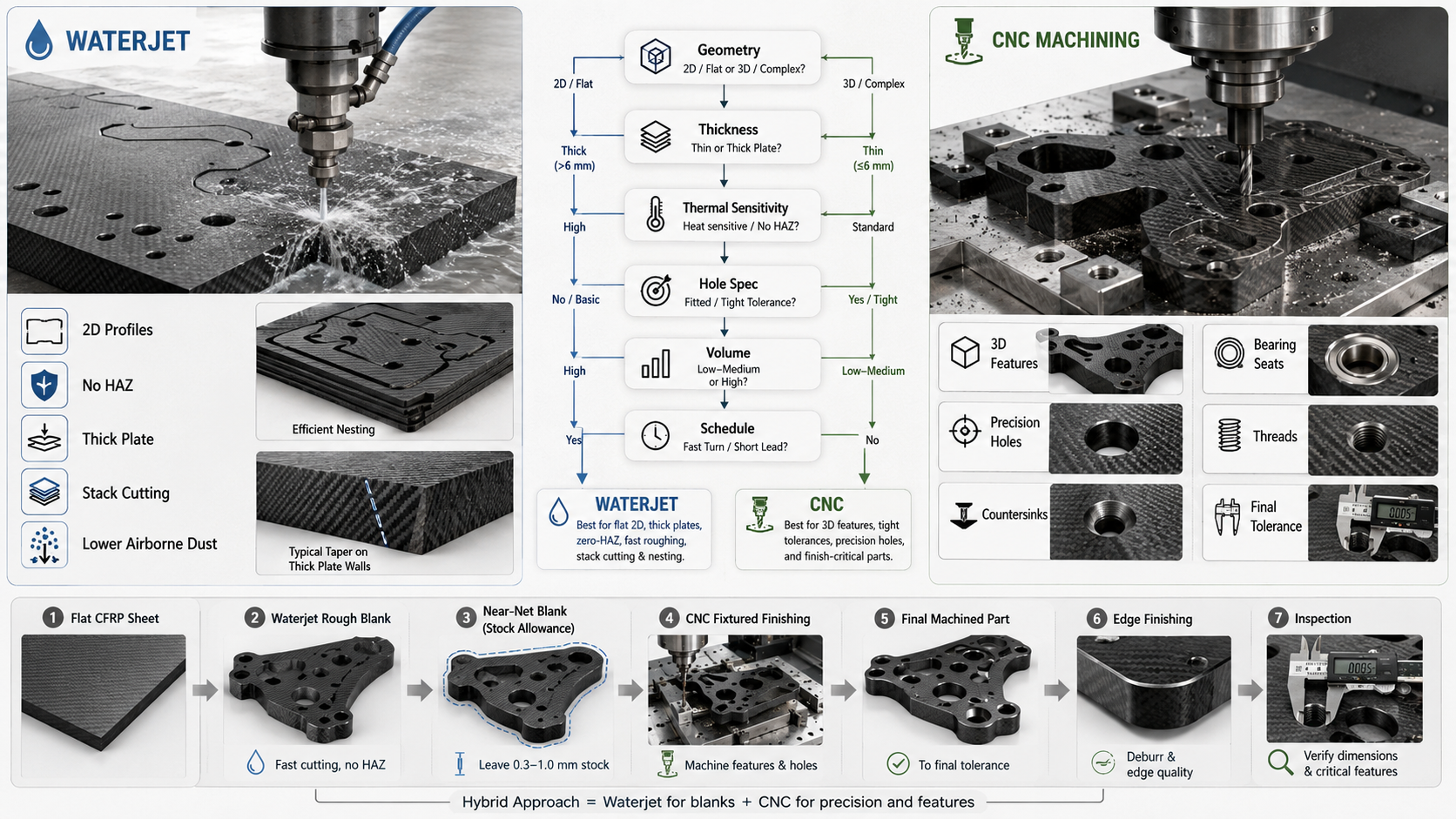
Waterjet and CNC machining both solve real problems in carbon fiber fabrication.
But they solve different problems.
The right choice depends on geometry, thickness, tolerance and what cannot go wrong.
Where Waterjet Wins
Waterjet is strong for thick 2D plate work.
It can handle carbon fiber from 0.5 mm up to 30 mm with no heat-affected zone.
There is no resin scorching and no HAZ. For parts near bond lines or fatigue-sensitive structures, zero thermal input matters.
Waterjet also helps with dust control. Abrasive waterjet flushes debris away in the water stream, lowering airborne fiber compared with dry CNC milling.
Waterjet is also useful for multi-sheet stacking. If you need 20 identical brackets cut from 3 mm plate, stacked cutting and nesting can improve material use.
Material savings can run 20–35% over single-sheet methods.
Where CNC Machining Wins
CNC machining wins when the part requires:
-
3D geometry
-
Controlled holes
-
Tight-tolerance holes
-
Countersinks
-
Stepped pockets
-
Compound-angle holes
-
Bearing seats
-
Locating pin holes
-
Threads
-
Final tolerance after blanking
-
Complex trimming
-
Surface-critical finishing
Waterjet is a 2.5D process.
It can handle many flat profiles, but it cannot replace CNC for varying contours, precision holes, countersinks, stepped pockets and complex 3D features.
Waterjet may cut through-holes to strong positional accuracy, but wall taper in thick plate above 15 mm can reach 0.05–0.2 mm.
Bearing seats and locating pin holes usually need CNC drilling or finish reaming.
The Decision Framework
Use this order.
|
Decision Point |
Practical Rule |
|---|---|
|
Geometry |
Complex 3D features, ribs, bosses, countersinks and stepped pockets go to CNC. Flat profiles move to the next decision. |
|
Thickness |
For ≤5 mm with tight tolerances of ±0.05 mm or better, choose CNC. For 5–30 mm 2D contours and multiple pieces, waterjet can be efficient. |
|
Thermal sensitivity |
If zero HAZ is required near bond lines or fatigue-critical zones, waterjet has an advantage. |
|
Hole specification |
Simple through-holes at ±0.1–0.2 mm may fit waterjet. Fitted holes, threads and tapered bores need CNC. |
|
Volume and schedule |
Simple prototype blanks may favor waterjet. High-precision 3D structural parts favor CNC with dedicated fixturing. |
The Practical Hybrid Route
For many production workflows, the best answer is not CNC or waterjet.
It is both.
Waterjet for blanks, CNC for final features.
A practical route is:
-
Waterjet rough-cuts the contour.
-
Leave 0.3–1.0 mm stock.
-
CNC finishes to tolerance.
-
CNC drills precision holes.
-
CNC machines countersinks, bearing seats or 3D features.
-
Edge finishing and inspection complete the part.
Neither process is secondary.
Each does what the other cannot.
Carbon Fiber CNC Machining Applications and Industry Standards

Carbon fiber CNC machining sits at the center of production across aerospace, motorsport, UAV manufacturing, automotive, robotics and sporting goods.
Each sector has different tolerance and inspection expectations.
UAV and Drone Frames
Typical parts include:
-
Arm plates
-
Electronics enclosures
-
Gimbal mounts
-
Camera plates
-
Lightweight frame components
Standard material often runs 1.5–3.0 mm CFRP sheet.
High-spec commercial drone frames may require CNC routing to hold ±0.025 mm on contour and hole position.
For UAV frames, hole position and clean edges affect assembly fit, vibration behavior and structural repeatability.
Aerospace Structural Parts
Typical parts include:
-
Bulkhead stiffeners
-
Equipment brackets
-
Fairing attachment rings
-
Panel stiffeners
-
Structural interfaces
Fastener hole groups often require ±0.02–0.05 mm.
Large panel profiles may hold within ±0.25 mm, with tighter local tolerances on datum features.
Aerospace machining also requires strong inspection discipline, including CMM inspection and, where required, UT or X-ray NDT.
Automotive and Motorsport
Typical parts include:
-
Chassis reinforcement plates
-
Instrument panel backings
-
Pedal assemblies
-
Interior panels
-
Brackets
-
Aero components
Structural connection holes often hold ±0.05–0.10 mm.
Interior panels may run around ±0.2 mm, enough for assembly clearance and visible fit.
Motorsport parts may require tighter local control where the part connects to suspension, chassis or aerodynamic mounting points.
Sporting Goods
Typical parts include:
-
Skateboard decks
-
Bicycle clamps
-
Paddle components
-
Protective components
-
Lightweight brackets
Contour tolerances often hold around ±0.10 mm.
Metal-interface features may tighten to ±0.05 mm.
Certification and Quality Expectations by Sector
|
Industry |
Quality System |
Key Expectation |
|---|---|---|
|
Aerospace |
AS9100 + ISO 9001 |
CMM inspection, ±0.02–0.05 mm critical dimensions, UT/X-ray NDT where required |
|
Automotive |
IATF 16949 + ISO 9001 |
PPAP capability, material traceability, repeatability |
|
UAV |
ISO 9001; AS9100 for military-grade |
Batch consistency, ±0.025–0.05 mm hole position |
|
Sporting goods |
ISO 9001 + product safety standards |
Edge quality, surface consistency, fatigue performance |
At HyperX Carbon, we machine CFRP from 1.0–20 mm across multiple sectors.
Our range includes 2D drone frames held to ±0.025 mm and 5-axis aerospace components where critical interfaces stay within ±0.05 mm.
Carbon fiber does not forgive guesswork.
Every toolpath decision, spindle speed, drill entry angle, dust-control step and finishing sequence either protects the laminate or damages it.
What to Send Before Requesting a Carbon Fiber CNC Machining Quote
A carbon fiber CNC machining quote is only as accurate as the information behind it.
Before asking for price and lead time, send the details that allow the manufacturer to choose the right tooling, machining route, fixturing, dust-control setup and inspection method.
Required Files
Send:
-
CAD file
-
DXF file for flat profiles
-
STEP file for 3D or multi-face parts
-
2D drawing
-
Part revision
-
Hole table if available
-
Assembly drawing if hole fitment matters
Material and Laminate Details
Include:
-
Carbon fiber sheet or part thickness
-
Laminate type
-
Woven, UD or quasi-isotropic structure if known
-
Surface side orientation
-
Visible face requirement
-
Whether material is supplied by buyer or HyperX Carbon should supply it
-
Whether the part is plate, molded part, tube, panel or custom layup
Hole and Edge Requirements
Specify:
-
Hole diameter
-
Hole position tolerance
-
Whether holes are clearance, fitted or bearing interfaces
-
Countersink requirements
-
Delamination factor limit if applicable
-
Exit-face quality requirement
-
Edge fray limit
-
Edge break requirement
-
Grade 0 / Grade 1 edge expectation if applicable
-
Whether edges require sealing
Surface and Finishing Requirements
Clarify:
-
Raw machined edge
-
Sanded edge
-
Deburred edge
-
Sealed edge
-
Bonding preparation
-
Coating preparation
-
Visible carbon protection
-
Clear coat or paint after machining
-
Surface roughness requirement
-
Packaging protection for cosmetic faces
Quantity and Production Stage
Tell the supplier:
-
Prototype quantity
-
First article quantity
-
Batch quantity
-
Annual volume
-
Expected repeat order schedule
-
Target lead time
-
Inspection requirements
-
Industry application
-
Critical failure risk
At HyperX Carbon, this information helps us review whether the project should use:
-
3-axis CNC
-
4-axis CNC
-
5-axis CNC
-
Waterjet blanking + CNC finishing
-
Dedicated fixture
-
Backing plate drilling
-
Compression tooling
-
PCD or CVD tooling
-
Edge sealing
-
CMM inspection
-
Custom packaging for visible surfaces
A complete RFQ protects both cost and part quality before machining starts.
FAQ: Carbon Fiber CNC Machining Questions
Can Carbon Fiber Be CNC Machined?
Yes.
Carbon fiber can be CNC machined into plates, profiles, holes, slots, brackets, frames, housings and structural components.
But CFRP requires composite-specific tooling, controlled feed rates, shallow passes, dust extraction and careful fixturing.
It should not be treated like aluminum or steel.
What Is the Best Tool for Cutting Carbon Fiber?
For repeat production, PCD or CVD diamond-coated carbide tools are usually preferred.
PCD offers toughness, re-sharpening and predictable performance under less-than-perfect fixturing.
CVD diamond-coated carbide offers very high hardness and long life in stable trimming.
For edges where both top and bottom faces matter, compression bits are often the best choice.
What Speeds and Feeds Are Used for Carbon Fiber CNC Cutting?
A working baseline is:
-
Spindle speed: 18,000–25,000 RPM
-
Feed rate: 1,000–1,500 mm/min
-
Chip load: 0.05–0.08 mm/tooth
-
Depth of cut: 0.5×D per pass, maximum 1×D
Actual settings depend on thickness, tool diameter, fiber orientation, fixture stability and edge requirement.
How Do You Prevent Delamination When Drilling Carbon Fiber?
Control thrust force.
Use composite-specific drills, low feed rate, backing support, rigid clamping and reduced feed near exit.
For Ø4–6 mm PCD or CVD diamond-coated drills, feed may stay around 0.02–0.06 mm/rev.
For critical holes, avoid exceeding 0.10 mm/rev.
Backing plates are especially important for laminates thinner than 3 mm.
What Is a Good Edge Quality Standard for Carbon Fiber Trimming?
For high-quality structural edges, Grade 0 means zero visible delamination and interlaminar crack length under 0.05 mm.
A practical process uses roughing, semi-finishing and one or two finishing passes.
Do not rely on one aggressive cut.
Should Carbon Fiber Edges Be Sealed After Machining?
For exposed structural edges, sealing is often recommended.
Exposed fiber ends can absorb moisture, weaken fiber-matrix adhesion and start edge delamination over time.
Low-viscosity epoxy sealant, polyurethane coating or UV-cure acrylic can be used depending on the application.
Is Carbon Fiber Dust Dangerous for Machines?
Yes.
Carbon fiber dust is abrasive and conductive.
It can damage bearings, guideways, ballscrews and electrical systems.
Professional CFRP machining should use dust extraction, HEPA filtration, negative-pressure enclosures where appropriate, sealed electrical cabinets and no compressed-air blowdown into electronics.
Should I Choose CNC Machining or Waterjet Cutting?
Use waterjet for simple 2D blanks, thick plate, zero heat-affected zone requirements and nested multi-sheet cutting.
Use CNC for precision holes, countersinks, bearing seats, stepped pockets, 3D geometry and final tolerance.
For many production projects, the best route is:
Waterjet for blanks, CNC for final features.
What Tolerance Can Carbon Fiber CNC Machining Hold?
It depends on geometry, fixturing, material thickness and machine axis.
As reference:
-
Flat CFRP 3-axis work can hold around ±0.05 mm with strong vacuum fixturing.
-
UAV frame profiles may reach ±0.025 mm.
-
Aerospace critical holes may require ±0.02–0.05 mm.
-
HyperX Carbon machines CFRP from 1.0–20 mm, including 2D drone frames held to ±0.025 mm and 5-axis aerospace components with critical interfaces within ±0.05 mm.
Final Takeaway
Carbon fiber CNC machining is not a trial-and-error process.
It requires the right tooling, controlled speeds and feeds, drilling strategy, trimming allowance, edge finishing, dust extraction, fixturing and inspection.
The best machining partner is not the one that says “we can cut carbon fiber.”
It is the one that can explain how they control:
-
Delamination
-
Fiber pull-out
-
Drill breakout
-
Hole tolerance
-
Edge fray
-
Dust
-
Tool wear
-
Fixture error
-
Final inspection
Send HyperX Carbon your CAD file, DXF file, 2D drawing, material thickness, laminate type, hole tolerance, edge requirement, surface requirement, quantity and application background.
Our engineering team can review whether your part should use 3-axis, 4-axis, 5-axis, waterjet blanking plus CNC finishing, dedicated fixtures, composite drilling strategy or edge sealing before quotation.
The material is unforgiving. Your machining process should be too.