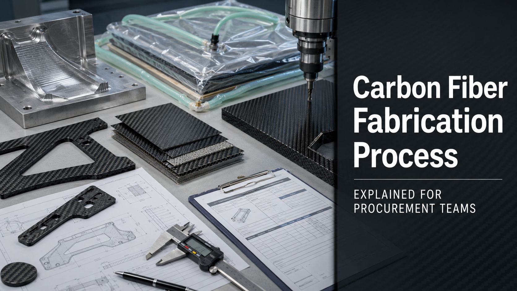
Picking the wrong carbon fiber molding process costs more than money.
It can weaken structural integrity, delay production, increase tooling waste, and lock your project into a manufacturing route that cannot scale.
Every process decision affects four things:
- Part quality — fiber consolidation, fiber volume fraction, void content, and defect risk
- Tooling investment — from low-cost soft molds to expensive autoclave-grade or matched steel tools
- Cycle time — from hours per cure cycle to minutes per molded part
- Unit cost — because the process you choose today defines the cost structure tomorrow
An aerospace bracket may need autoclave-level consolidation and strict void control.
A prototype enclosure may be better served by vacuum bagging.
A high-volume automotive panel may need compression molding.
A large structural fairing may fit resin infusion better than either autoclave or compression molding.
The point is simple: there is no single “best” carbon fiber molding process. There is only the right process for the part, volume, performance target, surface requirement, tooling budget, and validation path.
At HyperX Carbon, process recommendation does not start with what equipment is available. It starts with the buyer’s drawing, application, load case, geometry, tolerance, surface expectation, annual volume, and timeline.
Only after those inputs are clear can we recommend whether the project should use autoclave molding, compression molding, vacuum bagging, RTM, VARTM, resin infusion, or a hybrid route.
Carbon Fiber Molding Processes Compared: What This Guide Covers
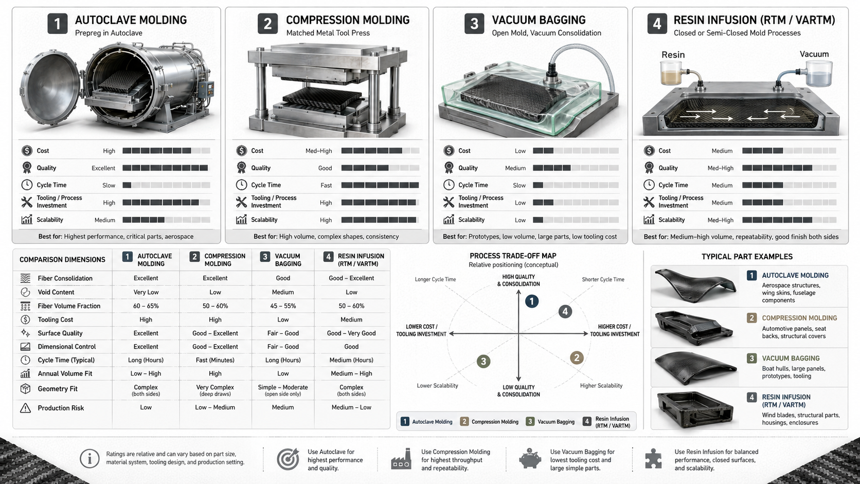
This guide compares the four main carbon fiber molding process families used in thermoset CFRP production:
- Autoclave carbon fiber molding
- Compression molding
- Vacuum bagging
- Resin infusion, including RTM and VARTM
Each process sits at a different point on the trade-off curve between cost, quality, speed, tooling investment, and scalability.
This guide explains:
- How each molding process works
- What fiber volume fraction and void content each method can usually achieve
- Where tooling cost becomes justified
- Which process fits which production volume
- How surface quality, tolerance, and structural performance change by process
- What information buyers should send before asking for a process recommendation
- Which questions procurement teams should ask before committing to a supplier
The goal is not to make buyers process experts.
The goal is to help procurement and engineering teams avoid the most expensive mistake in composite manufacturing:
choosing a process based on habit, quote price, or supplier preference instead of real project requirements.
What Is Carbon Fiber Molding and Why Process Choice Matters

Carbon fiber composites do not behave like metal.
With aluminum or steel, the material properties are mostly fixed before machining begins.
With carbon fiber, the manufacturing process helps create the material properties.
How fiber and resin are combined, compacted, cured, trimmed, inspected, and finished determines the final structural outcome.
Carbon Fiber Is a Process-Dependent Material
Carbon fiber carries the load.
The resin matrix transfers load between fibers, supports fibers against buckling, protects the laminate from the environment, and locks the structure into its final shape.
The balance between fiber and resin has a name:
fiber volume fraction, or FVF.
High-performance structural carbon fiber parts often target 55–65% fiber by volume.
The molding process is one of the main levers that decides whether the part reaches that target.
For example:
- Vacuum bagging with wet layup usually runs at about 1 bar of consolidation pressure. FVF often lands around 40–55%, and resin-rich zones are more common.
- Compression molding and prepreg hot-press methods push far higher force through a closed tool. FVF can exceed 60%, and void content can stay below 1–2% when the process is well controlled.
- Autoclave molding combines internal vacuum with external pressure and controlled heat, giving the highest consolidation level among the processes covered here.
That difference is not cosmetic.
It shows up in:
- Tensile strength
- Flexural modulus
- Interlaminar shear strength
- Fatigue life
- Dimensional stability
- Long-term reliability
Process Parameters Change Mechanical Performance
Cure temperature, cure pressure, hold time, cooling rate, resin viscosity, vacuum level, and demolding temperature can all change final part performance.
For compression molding of carbon fiber thermoplastics, cure temperature is often one of the most influential variables, ranking above hold time, pressure, cooling rate, and demolding temperature.
That matters for procurement because an off-spec cure cycle is not just a production delay.
It can reduce mechanical performance.
Geometry Also Changes the Correct Process
Continuous unidirectional laminates can reach tensile strengths of 1,500–3,000 MPa.
Short-fiber compression-molded parts may deliver only 30–60% of that directional performance, but they can fill complex three-dimensional geometry that continuous fiber cannot easily reach.
That is not automatically a weakness.
It is a process fit question.
A random chopped-fiber molded part may be suitable for distributed loads, ribs, bosses, covers, and complex shapes.
A continuous-fiber autoclave laminate may be required for directional stiffness, primary structure, or safety-critical load paths.
Process selection is an engineering decision. Procurement should not treat it as a supplier default.
Autoclave Carbon Fiber Molding: Highest Performance and Tightest Control
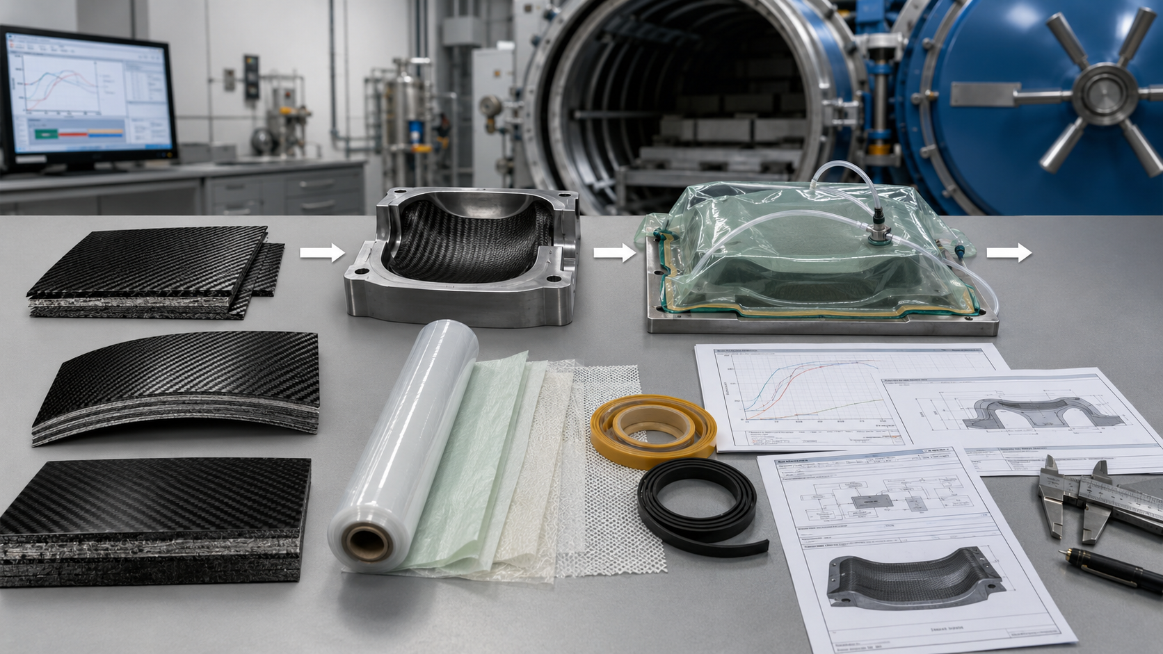
Autoclave molding is the high-control process used where structural consequence is serious.
Aircraft structures, wing skins, fuselage shells, Formula 1 monocoques, high-performance motorsport parts, and critical aerospace brackets often justify autoclave processing because the performance target leaves little room for porosity, poor consolidation, or uncontrolled cure variation.
How Autoclave Molding Works
Autoclave molding usually starts with prepreg carbon fiber.
Prepreg is carbon fiber fabric or unidirectional tape pre-impregnated with partially cured epoxy resin.
Before layup, prepreg typically thaws at room temperature for 4–8 hours until it reaches workable consistency.
Layup follows a controlled process:
- Plies are cut from CAD-generated flat patterns.
- Plies are stacked in a defined fiber-angle sequence.
- Every 3–5 layers, the stack may be vacuum-debulked.
- Debulking compresses the laminate, removes trapped air, and helps lock fiber angles before more plies are added.
After layup, the part is sealed inside a vacuum bag assembly.
That assembly may include:
- Release film against the laminate
- Perforated release film
- Breather fabric
- Tacky tape seal
- Vacuum port
- Bag film
- Leak check before cure
The bag is held near full vacuum, often around −0.1 MPa internal absolute pressure, and leak checks may run for at least 10 minutes before the part enters the autoclave.
Inside the autoclave, external gas pressure is applied, often with inert nitrogen.
Typical autoclave process ranges:
- Pressure: 6–7 bar, or 0.6–0.7 MPa
- Temperature: 120–180°C, depending on resin system
- Cure hold: 2–8 hours
- Total cycle time: often 4–12 hours, including load, heat-up, cure, cool-down, and unload
The key difference is consolidation pressure.
Vacuum bagging alone delivers about 0.1 MPa.
Autoclave molding can deliver 0.6–0.7 MPa external pressure while vacuum remains active inside the bag.
That pressure gap is one reason autoclave parts can achieve very low void content and high fiber volume fraction.
Performance Numbers Behind Autoclave Molding
High pressure and heat do specific things inside the laminate.
Temperature lowers resin viscosity. Resin flows into microscopic fiber gaps. Pressure drives compaction and suppresses void growth. Vacuum removes trapped air and volatile content.
The result is measurable.
| Performance Metric | Autoclave Prepreg | Vacuum Infusion / VARTM |
|---|---|---|
| Fiber volume fraction | 60–70% | 45–55% |
| Void content | <1% | 1–3%+ |
| Thickness deviation | ±1–3% | Higher variability |
That FVF gap of 10–15 percentage points can feed directly into structural performance.
With the same fiber and resin, higher consolidation pressure can improve:
- Tensile modulus by 20–30%
- Compression strength by 15–25%
Void control matters even more for fatigue.
Dropping void content from 2% to 1% can improve fatigue life by an order of magnitude in composite laminates.
That is why autoclave molding is not just a premium process.
For some applications, it is a risk-control requirement.
What Autoclave Performance Costs
Autoclave molding is expensive for several reasons.
A mid-size industrial autoclave — around 2–3 m diameter and 6–10 m length — can require seven-figure capital expenditure before installation, gas systems, controls, and maintenance.
Energy cost is also high. The process holds 120–180°C for hours under pressure and requires controlled cooling to prevent thermal stress.
In many composite manufacturing facilities, autoclave curing can take up more than 50% of total molding energy consumption.
Labor also adds cost.
A complex aerospace shell may require dozens to more than a hundred labor-hours per part for manual layup and debulking.
Autoclave molding usually makes economic sense when the part is:
- High value
- Low to mid volume
- Structurally critical
- Certification-sensitive
- Fatigue-sensitive
- Weight-sensitive
- Tolerance-sensitive
Typical annual volume may range from tens to several thousand units, depending on part size and program economics.
Where Autoclave Molding Belongs
Autoclave molding belongs where structural consequence justifies the cost.
Common applications include:
- Primary aircraft structures
- Wing skins and spars
- Fuselage sections
- Pressure frames
- Aerospace brackets
- Motorsport monocoques
- Formula racing structures
- Safety cells
- High-stiffness structural shells
- Critical suspension pickup zones
These applications often require:
- Void content below 1%
- FVF above 60%
- Tight dimensional tolerance
- Consistent cure data
- Traceable prepreg handling
- Process documentation
- NDT and inspection reports
Where Autoclave Molding Does Not Fit
Autoclave molding has hard limits.
Part size is capped by the autoclave interior.
Very large monolithic structures may be impractical.
The process also does not fit high-volume, price-sensitive products where the structural requirement does not justify long cycle time and expensive tooling.
For many industrial, automotive, consumer, and prototype projects, another process can deliver enough performance at lower cost.
Do not pay for autoclave control unless the part actually needs autoclave-level performance, certification, or risk reduction.
Compression Molding: High-Volume Carbon Fiber Part Production
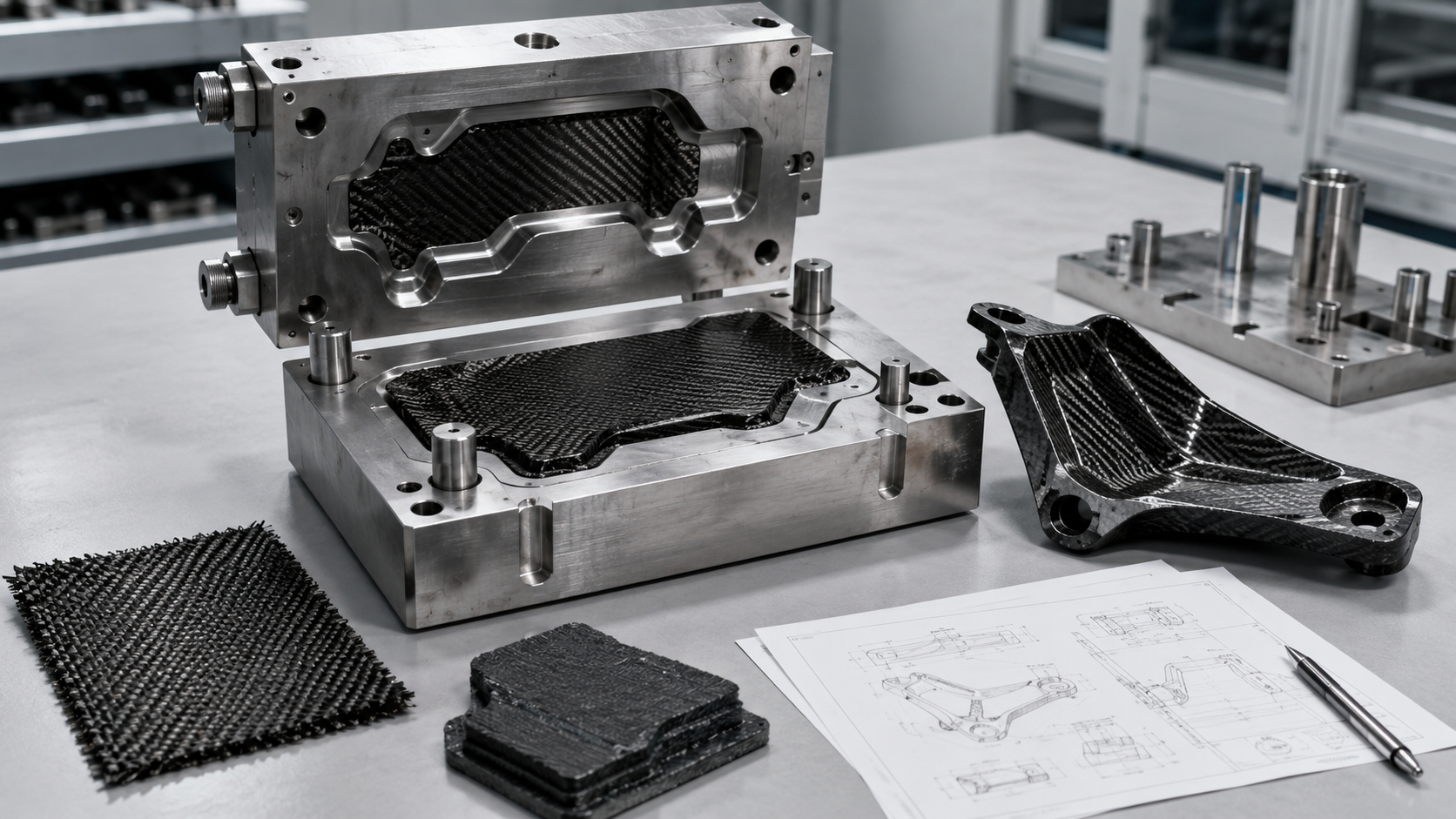
Compression molding exists for one reason:
volume.
When production targets move past thousands or tens of thousands of parts per year, slower processes become expensive.
Compression molding is often the practical route for high-volume carbon fiber panels, covers, enclosures, automotive parts, structural inserts, and forged carbon fiber components.
How Compression Molding Works
The basic process is straightforward.
A charge of material is placed into a heated matched metal tool.
That charge may be:
- SMC, or sheet molding compound
- BMC, or bulk molding compound
- Chopped carbon fiber preform
- Forged carbon fiber charge
- Continuous fiber preform for higher-performance compression molding
The press closes.
Pressure forces the material to flow into the cavity.
Heat triggers cure.
The part comes out close to final shape.
Typical thermoset compression molding parameters include:
- Mold temperature: 290–400°F, or 145–205°C
- Mold surface pressure: 1,000–2,500 psi, or 7–17 MPa
- Closing speed: up to 1,900 in/min for rapid fill
- Cycle time: 1–5 minutes for automotive structural panels
Cycle time is the main advantage.
At a 2-minute cycle, a single-cavity tool running one shift can produce close to 240 parts.
With multi-cavity tooling or multiple presses, output can scale far beyond what autoclave molding can support.
The Fiber Orientation Trade-Off
Compression molding gains speed and geometry flexibility, but there is a trade-off.
Chopped fiber SMC and forged carbon fiber systems spread fibers in random directions through the charge.
This helps the material flow into:
- Ribs
- Pockets
- Bosses
- Corners
- Complex 3D geometry
- Local thickness changes
But random fiber orientation limits directional mechanical performance.
Tensile strength and flexural modulus may land 30–60% lower than a continuous unidirectional laminate.
That does not make compression molding weak.
It means it is best suited for the right load case.
Compression molding is often strong for:
- Distributed loads
- Complex molded geometry
- Covers and housings
- Automotive panels
- Secondary structures
- High-volume functional parts
- Parts requiring fast cycle time and repeatability
It is not ideal for:
- Strong uniaxial load paths
- Primary aerospace structures
- Directional beams where fibers must run continuously
- Thin continuous skins requiring autoclave-grade consolidation
Continuous Fiber Compression Molding
Compression molding is not limited to chopped fiber.
Continuous fiber compression molding uses woven fabric or UD preforms with controlled ply orientation.
This can deliver:
- Fiber volume fraction above 60%
- Void content below 2%
- Better directional performance than chopped SMC
- Shorter cycle time than autoclave
For suitable geometries, it can close part of the performance gap between SMC and autoclave prepreg.
Where the Economics Tip
Compression molding requires significant tooling investment.
Matched steel tools or precision metal tools can run into high cost, especially for Class A surfaces, tight tolerances, or multi-cavity production.
The economics work when volume is high enough.
Typical crossover points:
- Automotive structural panels: compression molding may beat RTM and vacuum bagging above 10,000–20,000 parts per year
- Consumer electronics and sporting goods enclosures: payback may start around 5,000–10,000 parts per tool
At scale, automation becomes the advantage.
Robotic loading, controlled charge placement, programmatic press control, and automatic demolding can cut total unit cost 20–40% lower than RTM or vacuum bag alternatives when the volume is right.
For forged carbon fiber, a common process ratio is:
60% fiber / 40% resin by weight
Resin is often calculated at 1.25× fiber weight to ensure full wet-out before pressing.
When Compression Molding Fits
Compression molding is a strong candidate when:
- The part has complex 3D geometry
- Annual volume is high
- Cycle time matters
- Repeatability matters
- Class A or dual-side surface control is needed
- Directional strength demand is moderate
- The part can use chopped, forged, SMC, or controlled preform architecture
- Tooling investment can be amortized across volume
The bottom line:
If your part is complex, your volume is high, and your structural requirement does not demand autoclave fiber architecture, compression molding can be the most economical carbon fiber production route.
Vacuum Bagging: Flexible Low-Cost Molding for Prototypes and Small Batches
Vacuum bagging does not promise autoclave performance.
It promises flexibility, low tooling cost, and fast development.
For the right application, that is not a compromise.
It is the correct engineering and procurement decision.
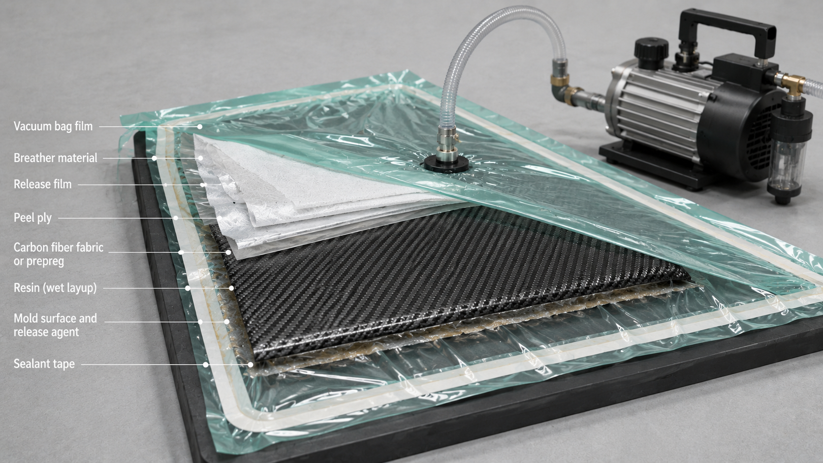
A buyer can produce a structural or semi-structural carbon fiber part with a simple mold, bag film, breather, peel ply, resin, and vacuum pump for a fraction of the tooling cost required by autoclave or compression molding.
How Vacuum Bagging Works
The setup is built layer by layer from the mold surface outward:
- Mold surface and release agent — wax or spray-applied release system
- Dry carbon fiber layers — fabric laid in required orientations
- Resin application — epoxy brushed, rolled, or worked into the fiber
- Peel ply — helps demolding and prepares the surface for secondary bonding
- Breather cloth — distributes airflow and absorbs excess resin
- Release film — perforated or solid, depending on resin bleed requirement
- Vacuum bag film — nylon, PE, or silicone bag film sealed with tacky tape
- Vacuum port and pump — connected through tubing and monitored with a gauge
Once the pump runs and the bag pulls down, atmospheric pressure consolidates the laminate.
The theoretical maximum consolidation pressure is around 1 bar, or 0.1 MPa.
That is the hard ceiling.
Autoclave molding applies 6–7 bar of external pressure on top of internal vacuum.
That gives autoclave around a 7× pressure advantage.
Fiber Content and Void Control
Wet layup with no vacuum often produces a fiber/resin mass ratio around 50/50.
Fiber volume fraction may land around 40–45%.
Add vacuum, perforated release film, and breather control, and experienced operators may reach 55–60% FVF.
But vacuum bagging is sensitive to technique.
Full vacuum can over-bleed thick wet laminates before complete wet-out is achieved.
For this reason, practitioners may target:
- 0.2–0.3 bar differential pressure for surface-quality parts
- ≥0.8 bar differential pressure for structural work
A vacuum regulator valve is better than simply clamping the pump line.
Controlled vacuum bag wet layup can produce void content around 1–2% by volume.
That can work for marine structures, sporting goods, motorsport secondary panels, custom prototypes, fairings, and small-batch structural parts where the design allows it.
It does not meet the <1% void threshold often expected for primary aerospace structures.
The Operator Variable
Vacuum bagging is flexible, but it is operator-sensitive.
The failure points are predictable:
- Resin mix ratio drift
- Vacuum timing problems
- Bag leaks at corners or edges
- Incomplete wet-out
- Over-bleeding
- Wrinkles
- Bridging
- Poor fiber angle control
A ±5% resin mix ratio error can shift gel time and cured mechanical properties.
Seal timing relative to resin pot life decides whether consolidation occurs before gel begins.
For standard epoxy systems, the maximum open time from mixing to sealed bag may be around 20–30 minutes.
A system such as EL2 + AT30 fast hardener may need at least 6 hours of maintained vacuum before pump shutdown.
These details belong in process cards.
Not in operator memory.
Where Vacuum Bagging Makes Sense
Vacuum bagging is often a good fit for:
- Prototype parts
- Development parts
- Small-batch custom fabrication
- Boat hulls
- Custom bodywork
- Architectural panels
- Wind instrument components
- Secondary panels
- Fairings
- Non-flight structural parts
- Parts where 55–60% FVF and 1–2% void content are acceptable
Vacuum bagging also works well when the buyer needs a low-cost process to validate geometry before investing in more expensive tooling.
Where Vacuum Bagging Does Not Fit
Vacuum bagging is not the right route when the part requires:
- Autoclave-level consolidation
- Void content below 1%
- Aerospace primary structure certification
- Highly repeatable high-volume production
- Tight tolerance on both sides
- High consistency across thousands of units
- Complex closed geometry
- Strong pressure-assisted compaction
The honest constraint is pressure.
At 1 bar maximum consolidation, vacuum bagging cannot match autoclave molding.
But when the specification allows its FVF and void range, vacuum bagging can be a highly practical and cost-effective carbon fiber molding process.
Resin Infusion, RTM and VARTM: Scalable Structural Composite Molding
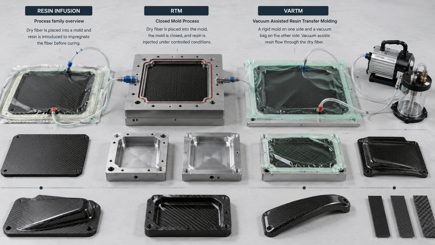
Resin infusion is a process family.
RTM, VARTM, and LRTM all share one idea:
dry fiber goes into the tool, resin is pulled or pushed through the preform, and the part cures as an integrated composite structure.
But the execution differences matter.
RTM: Resin Transfer Molding
RTM uses a rigid two-sided closed mold.
Resin is injected under low to moderate pressure.
RTM offers:
- Two finished surfaces
- Better dimensional control
- Repeatable flow path
- Shorter cycle time than vacuum-only infusion
- Good mid-to-high volume potential
- Controlled part thickness
The trade-off is tooling cost.
Matched metal dies are more expensive than single-sided VARTM tooling.
RTM is often suitable when the buyer needs dual-surface quality, repeatable cycle time, and consistent geometry.
VARTM: Vacuum-Assisted Resin Transfer Molding
VARTM uses one rigid mold face and a vacuum bag on top.
Atmospheric pressure pulls resin through the dry fiber preform.
No high-pressure injection equipment is required.
That changes the economics.
VARTM is often used for:
- Wind turbine blades
- Marine hulls
- Large aerospace fairings
- Large panels
- Lower to medium volume structural components
Advantages include:
- Lower tooling investment
- Practical large-part manufacturing
- One good mold-side surface
- Good structural consistency when flow is controlled
Limitations include:
- Bag-side surface not typically finished
- Thickness variability
- Dry spot risk
- Sensitivity to resin flow path
- Moderate dimensional precision compared with RTM
LRTM: Light RTM
LRTM sits between RTM and VARTM.
It uses lower clamping force, lower injection pressure, and lighter tooling than standard RTM.
It can deliver two-sided surfaces with lower tooling investment than full RTM, but material waste may be 15–20% higher than RTM because of edge trimming and lower resin fill precision.
LRTM is useful when buyers need a middle path between cost, complexity, and batch size.
Fiber Content and Flow Physics
Infusion performance depends on flow control.
VARTM can reach 60–70% fiber by weight on a reliable basis.
Standard RTM may target around 30% resin by weight, giving controlled fill and predictable flow paths.
Resin movement follows Darcy’s Law:
uD = −(K/μ)∇P
The key variables are:
- Permeability, K
- Resin viscosity, μ
- Pressure differential across the part
Higher permeability, lower viscosity, and a larger pressure gradient lead to faster fill and lower dry-spot risk.
Inlet and vent placement are not guesses.
For large parts, resin enters through planned distribution media and flow channels. These help the flow front advance evenly.
Problem areas include:
- Thick zones
- Corners
- Ribs
- Step changes
- Complex cross-sections
- Low-permeability zones
Local permeability changes can stall the flow front and create dry spots.
The fix may require:
- Zoned injection
- Extra vent points
- Multi-gate infusion
- Flow media adjustment
- Resin viscosity control
- Trial infusion validation
Where Each Infusion Process Fits
| Decision Factor | Choose RTM | Choose VARTM | Choose LRTM |
| Surface finish | Both faces | Mold face only | Both faces |
| Tooling cost | Higher | Lower | Moderate |
| Part size | Mid-size | Large | Mid-size |
| Batch volume | Medium–high | Low–medium | Medium |
| Dimensional precision | High | Moderate | Moderate |
Compared with autoclave, RTM and VARTM generally fall short on the lowest void content and highest FVF in the most demanding structural sections.
They are not usually the first choice for primary flight structure that requires sub-1% voids and aerospace certification packages.
But for large structural components with moderate wall thickness — wind energy, marine, industrial, automotive, and many large panel applications — RTM and VARTM can be the right balance between quality, tooling cost, and production practicality.
The straight answer:
- RTM — choose it when dual-surface quality and repeatable cycle time matter.
- VARTM — choose it when the part is large, tooling budget is limited, and one good surface is enough.
- LRTM — choose it when you need a middle ground between cost, complexity, and batch size.
Carbon Fiber Molding Processes Compared by Cost, Quality, Speed and Application Fit
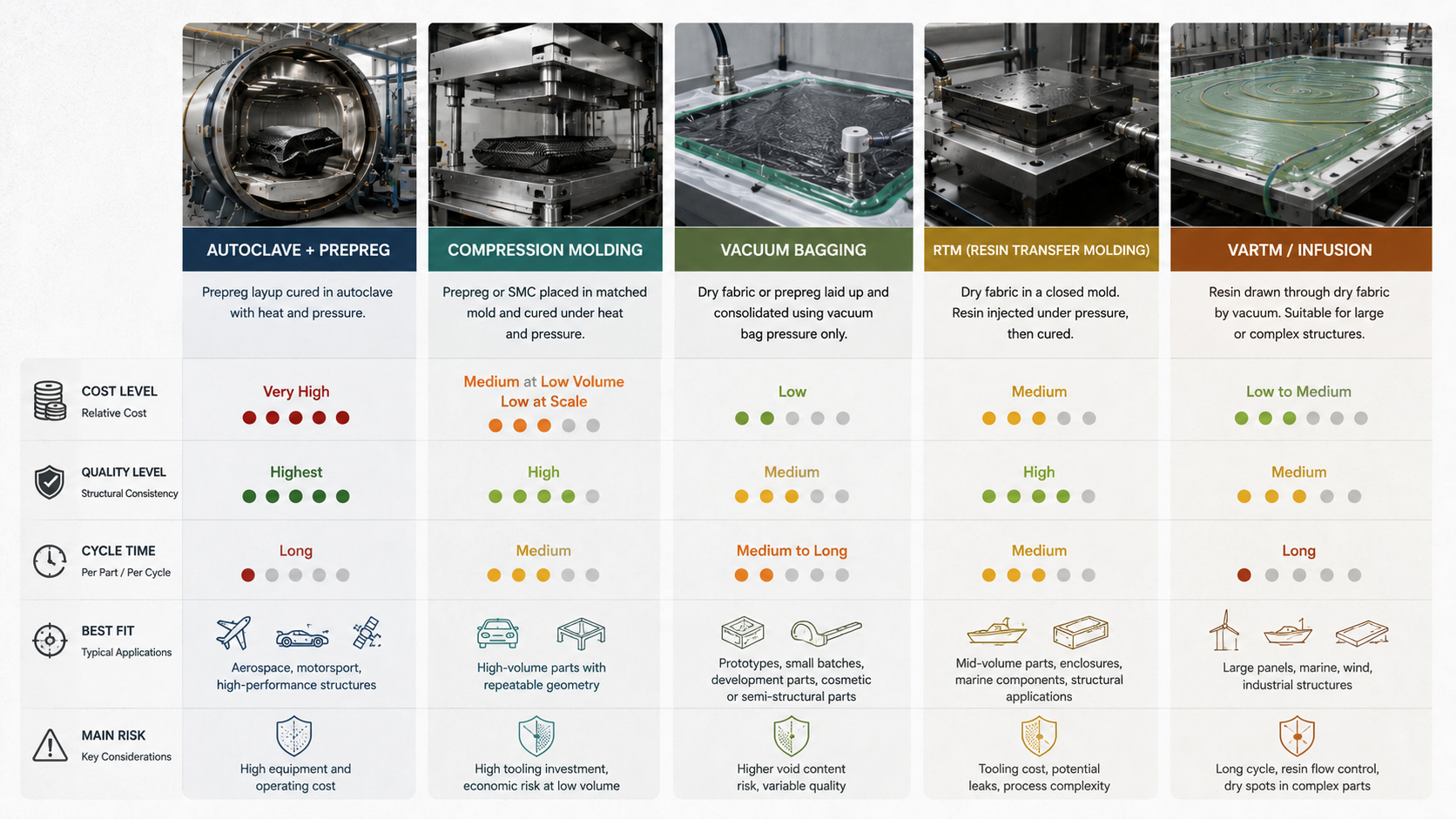
Four process families.
Four different cost structures, quality ceilings, and production rhythms.
| Process | Equipment Cost | Unit Cost | Quality Level | Cycle Time | Production Volume | Typical Industries |
| Autoclave + prepreg | Very high | Medium–high | Highest; aerospace-grade void control | Medium–slow | Low–mid volume, high-value parts | Aerospace, motorsport, defense |
| Compression molding / SMC | Medium–high | Low–medium at scale | High; Class A surface achievable | Fast; minutes per cycle | Medium–high volume | Automotive panels, enclosures |
| RTM / VARTM | Medium | Medium | Medium–high; consistent fiber control | Medium–fast | Medium volume | Auto structures, wind, marine |
| Vacuum bagging / wet layup | Low | Low upfront | Medium; operator-dependent | Medium | Small batch, prototypes | Marine, sporting goods, custom fabrication |
Fiber Volume Fraction and Void Content by Process
Fiber volume fraction and void content are not abstract metrics.
They decide whether a part passes qualification testing or fails on the bench.
Typical ranges:
- Autoclave + prepreg: FVF 55–65%+, voids <1%
- RTM / VARTM: FVF 45–60%, voids 1–3%
- Compression molding / SMC: FVF 30–50%, voids <2% in many controlled cases
- Vacuum bagging / wet layup: FVF 40–55%, voids 3–8% without tight process discipline
Where the Cost Crossover Happens
The right process changes with annual volume.
Useful procurement thresholds:
- Under ~1,000 parts/year: vacuum bagging or VARTM often wins on total cost because hard tooling and press investment cannot be amortized well.
- 5,000–20,000 parts/year: compression molding can start beating RTM on unit economics because minute-level cycle times and automation close the gap.
- Performance-critical at any volume: autoclave may be the correct choice when sub-1% void content, tight mechanical variation, and certification data are required.
Decision Priority Matrix
| Primary Goal | First Choice | Second Choice | Third Choice |
| Maximum performance | Autoclave + prepreg | RTM / VARTM | Compression molding |
| Lowest cost | Vacuum bagging | VARTM | RTM |
| Fastest cycle time | Compression molding | VARTM | RTM |
| Scalability | Compression molding | RTM / VARTM | Vacuum bagging |
The decision rule is straightforward:
- Low volume and tight budget → vacuum bagging
- Mid-volume with structural requirements → RTM or VARTM
- High volume with tight cycle-time pressure → compression molding
- Highest structural performance and lowest void requirement → autoclave
How to Choose the Right Carbon Fiber Molding Process for Your Project
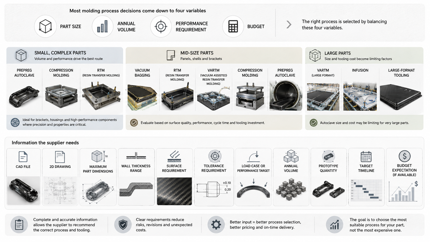
Four variables drive most carbon fiber molding decisions:
- Part size
- Annual volume
- Performance requirement
- Budget and tooling logic
Get clear on those four, and the correct process becomes much easier to identify.
Part Size Sets Hard Limits
For parts under 300 mm, such as small brackets, fairings, housings, and compact structural components, prepreg with autoclave or heated press can deliver precision. Wet layup with vacuum bagging may work if the budget is tight and performance requirements are moderate.
For parts between 300 mm and 1,500 mm, such as mid-size shells, body panels, aerofoils, and equipment covers, vacuum infusion, RTM, and compression molding may all be candidates.
For parts over 1,500 mm, such as boat hulls, wind blades, large fairings, and large body panels, VARTM and large-format LRTM often become more practical. Autoclave becomes difficult unless the application is high-value aerospace work with equipment size available.
Annual Volume Determines Tooling Logic
For fewer than 50 parts per year, low-cost soft tooling with wet layup or oven-cured prepreg may keep total project cost down, even if per-part labor is higher.
For 50–1,000 parts per year, RTM and vacuum infusion often enter their economic sweet spot. Matched or semi-matched tooling can spread cost across mid-batch production.
For more than 1,000 parts per year, compression molding becomes a serious candidate because cycle time can fall to 1–5 minutes per part.
For very high volumes, tooling cost becomes less important than cycle time, automation, and repeatability.
Performance Requirement Narrows the Field
Ask one direct question:
Does failure create a safety, certification, or structural consequence?
If yes, the process must support that risk level.
Primary aerospace and motorsport safety structures often need:
- Void content below 1–2%
- FVF above 55%
- Cure records
- NDT
- Material traceability
- Mechanical test evidence
- Process qualification
That pushes the project toward autoclave or highly controlled closed-mold routes.
Automotive structural panels, marine frames, industrial enclosures, and large equipment covers may not need autoclave. RTM and VARTM can deliver 50–60% FVF and 1–3% void content under good process control, which satisfies many non-flight applications.
Budget Sets the Floor
| Approach | Tooling Cost Range | Best Fit |
| Wet layup / vacuum bagging | Low; soft molds, a few thousand dollars | Prototypes, small batch |
| RTM / vacuum infusion | Mid; USD 10,000–100,000+ per tool depending on size and complexity | Mid-volume structural parts |
| Autoclave prepreg + precision metal tooling | High; tooling alone often exceeds USD 100,000; autoclave equipment reaches seven figures | High-value, low-volume flight or racing parts |
Common Process Selection Mistakes
The first mistake is chasing autoclave quality when the part does not need it.
For mid-volume, non-critical parts, autoclave processing might add 10–20% in mechanical performance over RTM, but it can multiply tooling and equipment cost several times over.
The second mistake is underestimating RTM and infusion process development.
Dry spots, premature gelation, and flow-front overlap do not only create scrap. They trigger trial cycles, vent changes, flow-media adjustments, and sometimes mold rework.
The third mistake is over-investing in hard tooling at low volume.
For anything under 50 parts per year, a full RTM tool plus injection equipment often cannot pay for itself before the program changes.
A soft mold with vacuum bag prepreg may cost more per part but less per program.
The right molding process should match the project stage, not only the target part shape.
What to Send Before Asking for a Process Recommendation
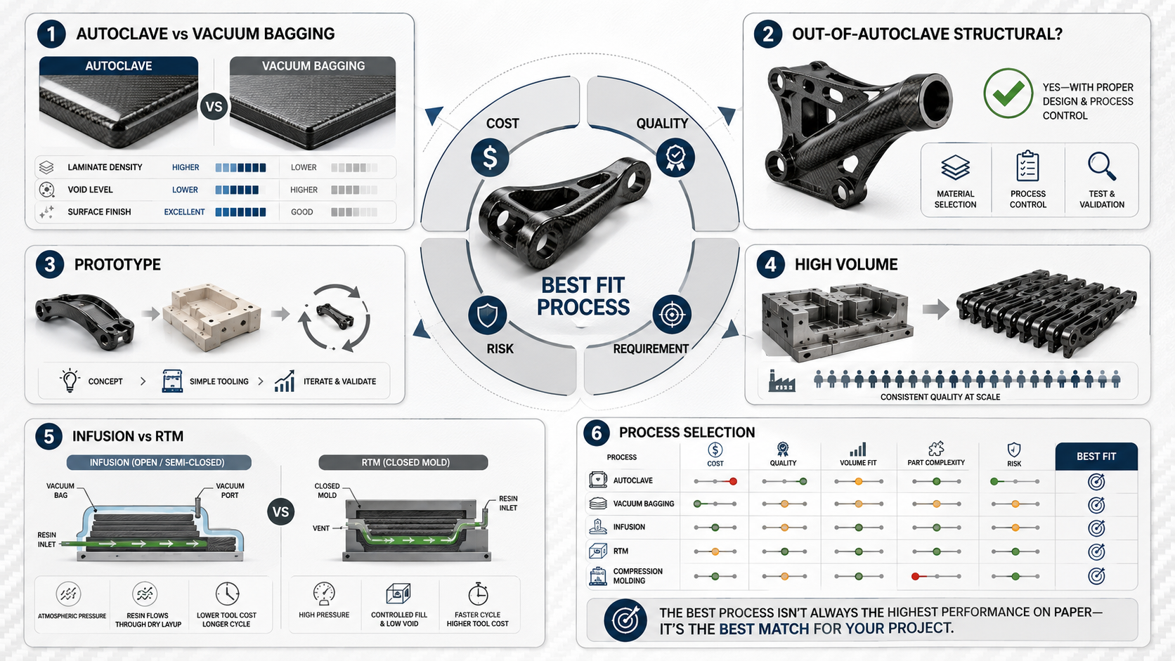
A supplier cannot recommend the right carbon fiber molding process without real inputs.
A message that only says “please quote carbon fiber part” is not enough.
Before asking HyperX Carbon or any qualified supplier for a process recommendation, send the information below.
Part Geometry
Send:
- 3D CAD file
- 2D drawing
- Maximum dimensions, L × W × H
- Wall thickness range
- Draft angle constraints
- Closed hollow sections
- Deep ribs
- Inserts
- Tight corner radii
- Local thickness changes
- Critical fitment surfaces
- Areas requiring CNC trimming or drilling
Geometry determines whether the part can be molded, infused, compressed, autoclaved, or needs a hybrid route.
Performance Targets
Send:
- Tensile strength target
- Flexural strength target
- Compression requirement
- Stiffness or deflection limit
- Safety factor
- Fatigue cycle count if relevant
- Impact requirement
- Load direction
- Reference metal part if replacing aluminum or steel
A process recommendation without load context is only a guess.
Surface Requirements
Send:
- Class A visible surface percentage
- B-side or hidden surface areas
- Acceptable pinholes
- Acceptable waviness
- Fiber pattern orientation
- Gloss requirement
- Clear coat or paint requirement
- Edge sealing requirement
- Surface inspection standard if available
Surface quality can change the process route and tooling method.
A cosmetic visible carbon fiber panel and a hidden structural bracket should not be quoted with the same finishing assumptions.
Annual Volume and Ramp Schedule
Send:
- Prototype quantity
- First article quantity
- Pilot batch quantity
- Annual volume
- Year-two and year-three forecast
- Production ramp timeline
- Target SOP date
- Hard delivery date
Volume determines whether low-cost tooling, RTM tooling, compression tooling, or autoclave processing is economically justified.
Working Environment
Send:
- Operating temperature range
- Fluid exposure
- UV exposure
- Moisture or humidity exposure
- Chemical exposure
- Indoor or outdoor use
- Electrical conductivity or insulation requirement
- Fire, smoke, toxicity requirement if relevant
Environment affects resin selection, cure route, surface protection, and testing.
Quality and Documentation Requirements
Send:
- NDT requirement
- Dimensional inspection requirement
- FAI requirement
- Material traceability requirement
- Mechanical coupon testing
- Certification requirement
- Inspection report format
- Packaging requirement
- Export documentation requirement
These inputs separate a real process recommendation from a generic proposal.
The more complete the brief, the faster a capable manufacturer can match the right carbon fiber molding process to your actual constraints — and provide a cost and lead-time estimate that is worth acting on.
FAQ: Carbon Fiber Molding Process Questions
What Is the Real Quality Gap Between Autoclave and Vacuum Bagging?
The gap is measurable.
Autoclave prepreg may cure at 112–140°C under about 0.4 MPa external pressure in some systems. It can deliver FVF of 55–65% and void content below 1%. Many aerospace OEM specifications target ≤0.5% void content.
Vacuum bagging runs at around −0.8 to −0.95 bar gauge with no external pressure. FVF often lands around 45–55%, with voids around 1–3% under good control.
Surface finish also shows the difference.
Autoclave parts can often achieve Class A quality directly from the tool. Vacuum-bagged parts may need 400–2000 grit sanding and polishing to reach a similar visible finish.
Quick decision rule:
- If the specification requires voids <1% and tensile strength within ±5% of design value, use autoclave.
- If the specification allows 2–3% voids and ±10% variation, high-quality vacuum bagging or VARTM may work.
Can Out-of-Autoclave Processes Handle Structural Work?
Yes — within clear limits.
RTM and VARTM can produce primary load-bearing beams, spars, chassis members, large panels, and structural shells in wind energy, marine, automotive, and industrial applications.
With good process control, closed-mold infusion can reach:
- FVF 50–60%
- Voids below 1.5–2%
- Tensile strength above 700 MPa in well-designed fiber architecture
- Modulus near 60–70 GPa in suitable laminates
OOA can be a strong autoclave alternative when:
- Part thickness is ≥2 mm
- Curvature is moderate
- Structural safety factor is ≥1.5–2.0
- Operating temperature is below 120°C
- The environment is non-pressurized
- Certification pathway accepts RTM or VARTM qualification
Two areas usually remain autoclave territory:
- Flight-critical aerospace structures
- Thin skins under 1.2 mm with complex double curvature and strict consolidation requirements
What Are Realistic MOQs, Lead Times and Certifications by Process?
| Process | Typical MOQ | Tooling Lead Time | Production Lead Time | Key Certifications |
| Autoclave prepreg | 1–10 pcs prototype; 50–100+ pcs series | 4–12 weeks | 2–6 weeks after tool release | ISO 9001, AS9100 |
| Vacuum bag / VARTM | 1–5 pcs | 2–8 weeks | 1–4 weeks | ISO 9001; DNV/ABS for marine structural use if applicable |
| RTM closed mold | 100–500 pcs/year | 8–16 weeks | 5–30 min/part cycle after SOP | ISO/TS 16949 or relevant automotive/aerospace qualification |
| Compression molding | ≥1,000 pcs/year | 8–20 weeks | Minutes per part | Automotive paint, thermal cycling and dimensional capability requirements |
These are not fixed rules.
They are starting benchmarks.
Actual MOQ and lead time depend on part size, tooling, surface requirement, material availability, validation, inspection, and supplier capacity.
What Process Parameters Should Buyers Know Before Specifying a Carbon Fiber Part?
A few numbers prevent expensive surprises.
For autoclave epoxy prepreg:
- Cure temperature may be 112–140°C in some systems
- Pressure may be around 0.4 MPa
- Void control is the main reason to use the process
For room-temperature wet layup epoxy:
- Pot life may be around 2 hours
- Full cure can take 48 hours under vacuum
For RTM injection:
- Vacuum may run −0.8 to −0.95 bar
- Injection pressure may be 1–3 bar above vacuum
- Cure temperature may be 80–140°C, depending on resin system
For compression molding / forged carbon:
- Target fiber-to-resin ratio may be 60:40 by weight
- Room-temperature post-cure may need at least 24 hours
For infused structural parts, specify:
void content ≤2% with NDT acceptance criteria
That usually means ultrasonic or CT scanning on the first article, plus statistical sampling across production runs.
Which Carbon Fiber Molding Process Is Cheapest?
For the lowest upfront cost, vacuum bagging or wet layup is usually cheapest.
But cheapest upfront does not always mean cheapest overall.
If the part needs tight tolerance, repeatable structure, high volume, or low void content, the low-cost process can create scrap, rework, and validation failure.
Cost must be evaluated as:
tooling + material + labor + cycle time + scrap + inspection + rework + lifetime production volume
Which Carbon Fiber Molding Process Is Best for High Volume?
Compression molding is usually the strongest candidate for high volume when the part geometry and structural requirement fit the process.
Its main advantage is cycle time — often 1–5 minutes per part — and compatibility with automation.
For high-volume parts with continuous fiber requirements, continuous fiber compression molding or RTM may also be considered.
Which Process Should I Use for a Prototype?
For early prototypes, vacuum bagging, wet layup, or oven-cured prepreg with soft tooling may be the best starting point.
The goal is to validate geometry, fit, surface concept, and basic performance before committing to expensive tooling.
For performance-critical prototypes, autoclave prepreg may still be required.
For production-representative prototypes, the prototype process should match the intended production process as closely as possible.
Final Takeaway
Choosing the right carbon fiber molding process is not about finding the most advanced method.
It is about matching the process to the project.
- Autoclave molding gives aerospace-grade precision, low void content, and high structural confidence.
- Compression molding supports high-volume production and repeatable cycle time.
- Vacuum bagging supports prototypes, low-cost tooling, and small-batch custom work.
- Resin infusion, RTM and VARTM fill the space between quality, scale, large-part capability, and tooling cost.
A part that performs and a part that fails may differ by one early decision:
the molding process.
Send HyperX Carbon your CAD file, drawing, application, performance target, surface requirement, volume, timeline, and working environment.
Our engineering team can review whether your project should use autoclave molding, compression molding, vacuum bagging, RTM, VARTM, resin infusion, or a hybrid route.
The right process exists. The first step is defining the part clearly enough to find it.