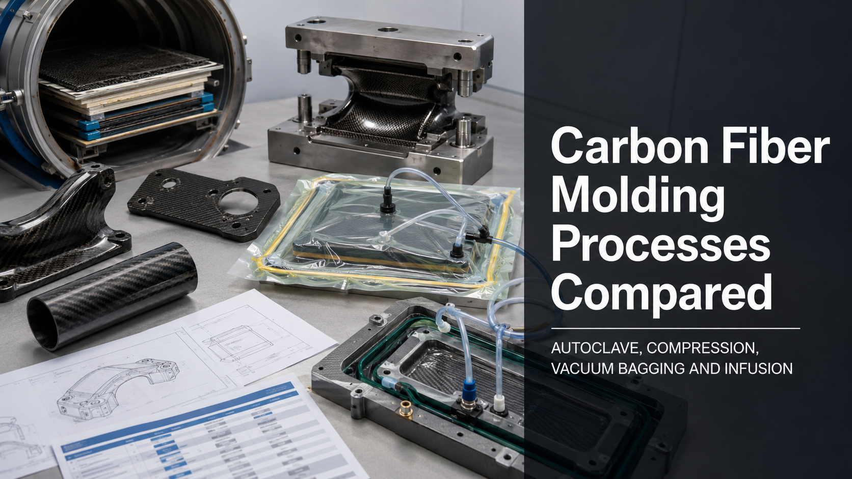
One bad batch of carbon fiber can wreck months of engineering work.
Failed layups, delaminated panels, tensile properties far below spec, unstable thickness, uncontrolled voids, poor ILSS, missing traceability, or weak inspection records can turn a custom CFRP project into scrap, delay, or field risk.
For buyers sourcing CFRP components, prepreg, fabric, tow, molded parts, CNC-machined plates, structural panels, UAV frames, automotive components, or industrial carbon fiber assemblies, the real quality problem rarely appears on delivery day.
It usually starts earlier.
It starts when the material specification is vague.
It starts when supplier certificates are accepted without scope review.
It starts when prepreg storage history is not checked.
It starts when layup, cure, NDT, inspection, and release rules are not defined before production.
Carbon fiber quality control is not a final inspection step. It is a pre-production risk-control system.
This guide gives buyers a practical carbon fiber quality control framework before production starts. It covers supplier qualification, raw material inspection, material specification, layup control, cure records, finished part inspection, NDT methods, common CFRP defects, documentation, traceability, and a ready-to-use pre-production checklist.
At HyperX Carbon, quality review starts before production, not after machining or shipment. We review material specification, tolerance, surface class, inspection requirements, traceability expectations, quantity target, and production route before the manufacturing plan is locked.
For CNC-machined carbon fiber plates, molded parts, UAV structures, automotive components, industrial brackets, visible carbon parts, and application-specific CFRP projects, the inspection plan may change depending on hole tolerance, edge quality, surface class, load condition, batch repeatability, and documentation requirements.
For projects requiring batch records, we align material lot, process route, inspection records, and release documentation before shipment.
Carbon Fiber Quality Control: What This Guide Covers

Carbon fiber quality control is not a single checkpoint.
It is a layered system that starts before a purchase order is issued and continues through material receiving, storage, layup, curing, machining, inspection, documentation, and shipment release.
A complete buyer-side carbon fiber quality review should cover ten areas:
-
Supplier certification and fiber grade verification
-
Incoming raw fiber, fabric, and prepreg inspection
-
Material specification and mechanical property targets
-
Laminate design and layup quality standards
-
Process parameter controls before production starts
-
Finished part dimensional, visual, and mechanical acceptance criteria
-
Non-destructive testing requirements
-
Mechanical testing and coupon qualification plans
-
Buyer-side inspection checklists, either on-site or through a third party
-
Documentation, traceability, and quality-loop closure
Some checks happen before supplier selection.
Some happen at incoming inspection.
Some belong to first article or pilot batch approval.
Others stay active across the full serial production run.
Together, they create complete composite quality assurance with no gaps and nothing left to guesswork.
The goal is simple: no material enters production, no part leaves production, and no batch is released without evidence.
Why Quality Control Before Production Saves Buyers From Costly Mistakes

Carbon fiber failures become expensive because they often appear after value has already been added.
A wrong material batch may not look wrong at receiving. A poor prepreg storage history may not be obvious before layup. A small vacuum leak may only appear later as voids, delamination, low ILSS, or failed mechanical coupons. A supplier process change may not show up until the second or third batch.
That is why quality control before production matters.
Catching a defect at incoming inspection costs very little. Catching it after tooling, layup, curing, CNC machining, finishing, packing, delivery, or assembly multiplies the cost quickly.
The cost logic is clear:
-
Reactive QC environments can see 15–25% of production lots needing rework or sorting.
-
Line stoppages in automotive and electronics can carry penalties of USD 10,000–50,000 per hour.
-
A single two-day line halt can cost USD 160,000–800,000, before adding expedited freight or reputation damage.
-
A pre-production QC investment of 1–3% of order value can protect against rework, scrap, delay, and schedule penalties that may reach 10–30% of order value.
In safety-critical applications, the downside can exceed the full order value once recalls, regulatory consequences, replacement cost, and customer trust are included.
Pre-production carbon fiber quality control is not overhead. It is risk arbitrage.
For buyers, the practical question is not only whether a supplier can make one acceptable sample.
The better question is:
Can this supplier prove that every batch can meet the material, process, inspection, and documentation requirements before production starts?
If the answer is not supported by documents, records, samples, inspection data, and traceability, the project is not ready for production.
Defining Material Specifications: The Starting Point of Carbon Fiber Quality Control

Specifications without numbers are not specifications.
They are wishes.
Before opening an inspection checklist or asking suppliers for pricing, buyers should lock the material and mechanical requirements that define acceptable quality.
A carbon fiber purchase specification should define:
-
Fiber type
-
Fiber grade
-
Tow size or fabric construction
-
Resin system
-
Prepreg or dry-fiber route
-
Cure system
-
Laminate target
-
Mechanical property targets
-
Inspection method
-
Test method
-
Acceptance rule
Get these wrong at the specification stage and everything downstream becomes expensive guesswork.
Choose the Fiber System Based on Application
Not all carbon fiber performs the same.
PAN-based fiber, pitch-based fiber, standard modulus, intermediate modulus, high modulus, and ultra-high modulus fiber behave differently. The right choice depends on load case, stiffness target, strength target, budget, process route, and application risk.
Tensile modulus across fiber grades can vary widely:
|
Fiber Type |
Typical Tensile Modulus |
|---|---|
|
Standard modulus PAN, such as T700 or T800 |
230–250 GPa |
|
Intermediate-to-high modulus PAN |
290–450 GPa |
|
Ultra-high modulus pitch-based fiber |
600–900 GPa |
Tensile strength tells a different story.
High-modulus pitch fibers gain stiffness but often give up strength. Typical high-modulus pitch fiber tensile strength may sit around 3–4.5 GPa, compared with 5.5–7.0 GPa for high-strength PAN grades.
That distinction matters.
A part that needs stiffness may not need the same fiber as a part that needs impact tolerance, fatigue resistance, bolted-joint strength, or high tensile load capacity.
A practical grade-to-load-case map looks like this:
|
Application |
Recommended Fiber |
Key Laminate Target |
|---|---|---|
|
Aerospace structure |
PAN mid/high modulus, such as T800 or T1000 |
Tensile strength ≥1500 MPa; modulus ≥130 GPa |
|
Automotive mass production |
Standard modulus PAN |
Tensile 600–1200 MPa; flexural modulus 40–80 GPa |
|
Industrial robotics or wind blade structures |
High modulus PAN |
ILSS ≥40–60 MPa; flexural modulus 70–140 GPa |
|
Sports equipment |
Standard PAN with local high-modulus reinforcement |
Flexural modulus 80–150 GPa |
At HyperX Carbon, material review is tied to application, load direction, surface requirement, tolerance, production volume, and process route. A visible automotive trim part, a UAV frame plate, a robotic bracket, and a structural aerospace interface do not need the same quality-control plan.
Lock In Four Mechanical Benchmarks Before Asking for a Quote
A purchase specification should set minimum targets across four properties at the laminate level, measured in the primary load direction.
|
Mechanical Benchmark |
Why It Matters |
|---|---|
|
Tensile strength |
Sets maximum load capacity and safety margin |
|
Compressive strength |
Controls bending capacity on compression-side flanges |
|
Interlaminar shear strength |
Indicates fiber-matrix and ply-interface bonding quality |
|
Tensile and flexural modulus |
Controls stiffness, deflection, fit, and NVH behavior |
Tensile strength sets the maximum load capacity and safety margin. Too little tensile strength can lead to sudden, brittle fiber fracture under peak load.
Compressive strength deserves special attention. It may run 20–40% below tensile strength in the fiber itself, and it often controls bending failure on the compression side of a beam or panel. Skip compression strength and a part may fail in bending even when the tensile numbers look strong.
Interlaminar shear strength shows the bond quality between fiber, matrix, and ply interfaces. Aerospace CFRP often targets 50–70 MPa ILSS. Industrial structural parts often target 40–60 MPa.
Any part with bolt holes, cutouts, bonded joints, inserts, or machined interfaces should include ILSS in the acceptance standard.
Tensile and flexural modulus govern stiffness and deflection. Too low and fit, vibration, and NVH can degrade. Too high without matching ILSS and impact tolerance can raise the risk of brittleness and delamination.
Reference the Right Standards
A target number means little without a test method.
Specify both together:
|
Property |
Common Test Method |
|---|---|
|
Tensile |
ISO 527 / ASTM D3039 |
|
Flexural |
ISO 14125 / ASTM D7264 |
|
ILSS |
ISO 14130 / ASTM D2344 |
|
Compression |
ASTM D6641 / ASTM D3410 |
For supplier qualification, ISO 9001 is the floor for general industrial work. Aerospace projects usually require AS9100 with current third-party certification and a scope that matches the relevant composite process.
Buyers should also define the acceptance basis:
-
Mean value
-
Characteristic value
-
A-basis or B-basis value
-
Minimum single-specimen value
-
Batch release threshold
A specification that says “high strength carbon fiber” without a number, test method, or acceptance rule leaves too much room for dispute.
And in a quality dispute, vague specifications usually hurt the buyer.
Supplier Qualification Checklist: How to Evaluate a Carbon Fiber Manufacturer Before Committing

Certificates are useful.
But certificates alone do not prove production control.
Certifications get framed. Processes get ignored. That gap is where supplier risk hides.
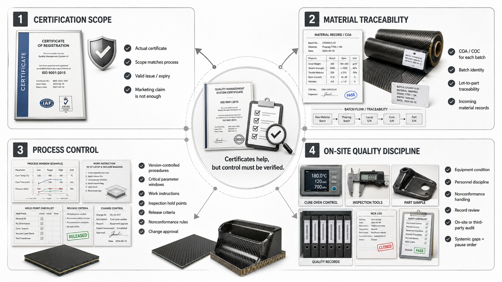
Before committing to a carbon fiber supplier, buyers should check four areas: certification scope, material traceability, process control, and on-site quality discipline.
Each checkpoint targets a specific failure pattern. Together, they separate suppliers who can perform from suppliers who only look capable.
Checkpoint 1: Certifications and Scope
Request the actual certificate, not only a marketing claim.
Not a brochure.
Not a letterhead statement.
Not a screenshot with missing scope.
Check:
-
Certificate copy
-
Current scope page
-
Expiry date
-
Certifying body
-
Facility address
-
Process scope
-
Product scope
Immediate red flags include:
-
Certificate expired or within 60 days of expiry
-
Scope does not cover carbon fiber manufacturing or the specific process being purchased
-
Certifying body cannot be confirmed through a third-party source
-
Supplier provides promotional material instead of the formal certificate
-
Facility address does not match the production site
For standard industrial carbon fiber parts, ISO 9001 is the minimum floor. For aerospace work, AS9100 is usually required, and the scope must cover the specific product and process.
“Composite manufacturing” in general terms is not always enough.
Checkpoint 2: CoA, CoC, and Material Traceability
Every incoming material batch should have a Certificate of Analysis or Certificate of Conformance.
No certificate, no receipt.
This is not paperwork for paperwork’s sake. Major carbon fiber supply chains enforce certificate control because material identity is the first quality gate. The same standard should apply to your supplier.
Pull up the CoA or CoC and match these fields against the physical delivery and your purchase order:
-
Batch number
-
Reel or lot number
-
Specification number
-
Quantity shipped
-
Production date
-
Test items
-
Test results
-
Signatory
-
Packaging label
-
Internal lot record
Go beyond the certificate.
The supplier should be able to trace the finished part back to raw fiber, prepreg, fabric, resin, layup batch, cure run, machining batch, inspection result, and shipment lot.
Strong aerospace supply-chain rules require incoming materials to be acceptable, documented, and traceable. Your supplier should meet the same practical bar.
No chain on demand means no real traceability.
Hard stops include:
-
Certificates that do not match packaging labels
-
Inconsistent certificate data for the same batch
-
Missing lot numbers
-
Unapproved raw material substitution
-
No record of which material batch was used in which finished parts
Checkpoint 3: Process Control and Change Management
A supplier’s process documents reveal more than its sales presentation.
Ask for evidence of:
-
Version-controlled manufacturing procedures
-
Critical parameter windows
-
Work instructions
-
Inspection hold points
-
Release criteria
-
Nonconformance rules
-
Change approval procedure
Verbal explanations instead of controlled documents are already an answer.
Change management is where process discipline gets tested.
A formal written approval process should cover changes to:
-
Materials
-
Formulations
-
Resin systems
-
Fiber grade
-
Layup schedule
-
Tooling
-
Cure parameters
-
Equipment
-
Subcontractors
-
Inspection methods
-
Packaging or storage
Then ask for proof.
Request documentation from the last 3–5 change events. Check whether each one followed a closed loop:
-
Change request
-
Impact assessment
-
Customer approval when required
-
First-article verification
-
Document update
-
Implementation date
Disqualifying answers include:
-
“We change first, then notify customers.”
-
No historical change approval records
-
No defined trigger conditions for change review
-
No customer approval process for critical changes
For custom carbon fiber parts, a supplier process change can affect stiffness, surface quality, fit, void content, thickness, cure state, traceability, and repeatability.
That is why change control is not optional.
Checkpoint 4: On-Site Audit, Equipment, People, and MRB
A document audit has limits.
An on-site audit or qualified third-party audit shows what is written versus what is running on the floor.
Focus on three areas: equipment, personnel, and nonconformance handling.
|
Audit Area |
What to Check |
|---|---|
|
Equipment |
Calibration status, maintenance logs, re-verification records after stoppage or repair, and whether on-site equipment supports the claimed process capability |
|
Personnel |
Operator and inspector qualification, current training records, new employee qualification, temporary-worker qualification, defect-recognition training, and traceability training |
|
Nonconformance handling |
MRB process, physical quarantine zone, NCR records, root cause, disposition, responsible party, closure date, and customer approval for rework or use-as-is decisions |
Systemic gaps should pause the order.
Examples include:
-
Expired calibrations
-
Missing training records
-
MRB handled by word of mouth
-
No physical quarantine area
-
Nonconforming parts mixed with conforming stock
-
Rework or use-as-is disposition without customer approval
-
No named approver on nonconformance closure
A verbal call on the shop floor is not acceptable.
A practical minimum qualification threshold is:
|
Area |
Requirement |
|---|---|
|
Certification |
Valid ISO 9001 / AS9100 where required; scope matches product and process |
|
Traceability |
Batch-level chain to upstream lot; aligned with CoA or CoC |
|
Change control |
Written process with closed-loop samples available on request |
|
On-site audit |
Equipment, training, and MRB pass; any systemic gap pauses the PO |
At HyperX Carbon, supplier-style quality thinking also applies inside the production review. Before a project moves forward, we clarify what is controlled in material selection, process route, inspection, and documentation so that sample success can become repeat production stability.
Raw Material Inspection: What to Check on Carbon Fiber Tow, Fabric, and Prepreg
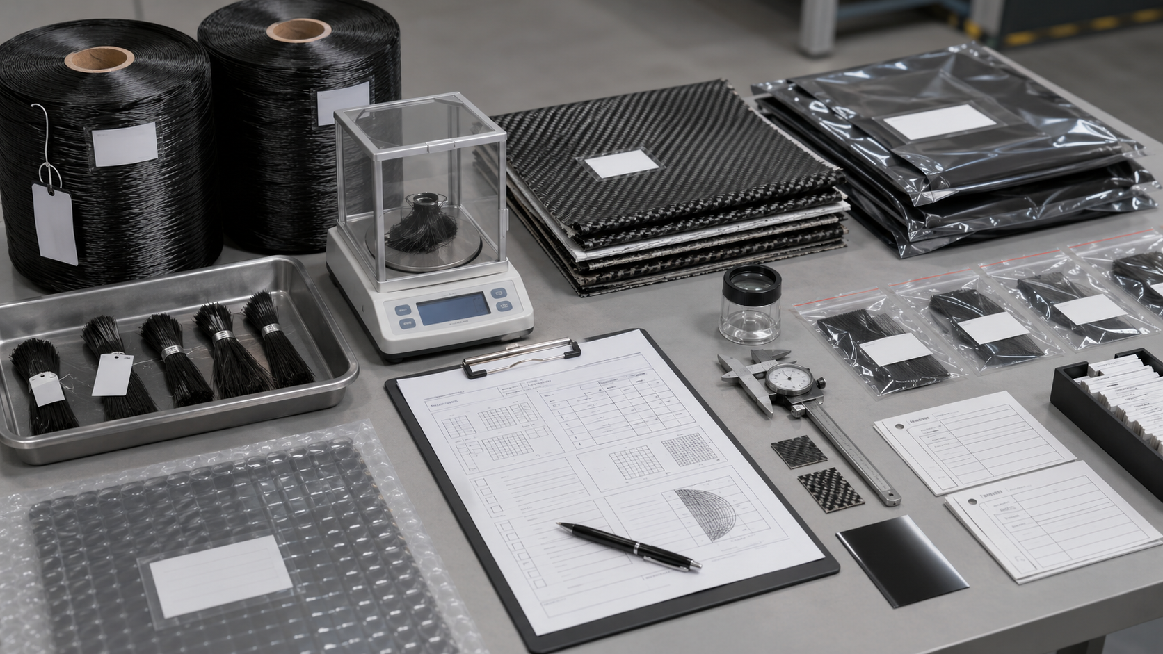
Raw material problems do not announce themselves.
They hide in a label discrepancy, off resin content, damaged fabric roll, fold in the fabric, prepreg storage excursion, moisture ingress, or packaging failure. Then they show up weeks later as delaminated panels, failed coupon tests, low ILSS, porosity, or rejected batches.
That is why incoming inspection matters.
No raw material should enter production until identity, physical condition, storage history, and documentation are confirmed.
Fiber Tow and Fabric Checks
Start with the label.
Confirm:
-
Fiber designation, such as T300, T700, or T800
-
Tow count, such as 3K, 6K, 12K, or 24K
-
Batch number
-
Lot number
-
Material code
-
Production date
-
Supplier name
-
Specification revision
-
PO match
Then verify the numbers against the physical material.
For tow, weigh a 10-meter sample to at least 0.01 g precision. Calculate linear density and compare it to the stated value.
A practical acceptance range is ±3–5%. Anything outside that range should trigger technical review before production.
For fabric, cut a 100 × 100 mm sample and weigh it. Convert the result to g/m² and compare against nominal GSM. Common nominal values include 200 g/m² and 300 g/m². A common acceptance window is ±5%.
Use a loupe or digital microscope to count yarns per 10 mm in warp and weft directions. Record both directions separately.
A fabric roll that looks acceptable from a distance can still have yarn count drift, displacement, edge fray, or ply-flatness problems that affect layup quality.
Visual Rejection Criteria
Visual inspection needs written acceptance criteria before inspection starts.
Not after a questionable defect appears.
For carbon fiber tow, reject when:
-
Discoloration covers more than 5 × 5 mm in any spot
-
Discoloration runs longer than 50 mm along the length
-
Broken filaments exceed 3 per meter on a 1–2 m sample
-
Bundle fusion or nodules exceed twice normal bundle diameter and extend more than 5 mm
-
Foreign matter larger than 1 mm appears in a 10 m inspection segment
For woven fabric, reject when:
-
Yarn displacement shifts more than one yarn spacing inside a 300 × 300 mm inspection zone and appears more than twice
-
Visible pattern distortion appears in more than two locations within the inspection zone
-
Creases exceed 1 mm height or 20 mm length
-
Creases break ply flatness
-
Edge fraying extends more than 5 mm in width
-
Edge fraying runs longer than 100 mm without break
For prepreg fabric under backlit inspection, reject when:
-
A single dry spot exceeds 100 mm²
-
Any dry area spans the full width
-
Resin-rich bright zones indicate unacceptable resin distribution
-
Moisture, punctures, or packaging damage are visible
Prepreg-Specific Checks
Prepreg needs checks that dry tow and dry fabric do not.
Storage and resin condition directly affect cure quality.
Check:
-
Resin content
-
Volatile content
-
Cold-chain history
-
Remaining shelf life
-
Cumulative out-time
-
Bag integrity
-
Tack
-
Bend behavior
Aerospace-grade carbon/epoxy prepreg commonly targets 35–40 wt% resin content, with a tolerance of ±2–3%.
Resin content can be checked with burn-off methods such as ASTM D3529 or ASTM D3530. The sample is weighed, resin is removed under controlled temperature, and fiber fraction is calculated.
Values below 32% or above 42% require technical review because they can affect fiber volume fraction, wet-out, ILSS, void content, and surface quality.
Volatile content should usually stay at ≤1–2 wt%.
Too high, and void formation can occur during cure.
Too low, and the resin may have already started to advance. That means reduced flow, poorer interface wetting, and weaker ply-to-ply bonding.
Storage should be verified at receiving.
Most carbon/epoxy prepregs require −18°C storage, controlled humidity below 50% RH, and sealed packaging. Any temperature excursion above 0°C should be logged against out-life. Temperature swings beyond ±5°C should be reviewed.
Reject prepreg packaging for:
-
Vacuum foil puncture
-
Seal failure
-
Visible moisture ingress
-
Missing storage label
-
Missing out-time record
-
Certificate mismatch
A compromised bag can lead to absorbed moisture. Absorbed moisture can create microporosity at fiber interfaces after cure. Published composite quality data commonly shows interlaminar shear strength losses in the range of 10–20% when moisture and cure quality are not controlled.
A simple functional check helps catch aging or storage problems.
At room temperature, fold a prepreg strip 180° without pressing it flat. Cracking or resin whitening on the outside of the bend can indicate over-aged or badly stored material.
Press two plies together with a roller, then pull them apart. Tack should feel consistent and moderate.
Dead-low tack can indicate pre-cure.
Excessive tack can indicate resin content or formulation problems.
Document Verification at Receiving
Every batch should be checked at the dock.
Not after it is already in storage.
Cross-check:
-
Batch and lot number
-
Fiber grade and tow specification
-
Resin type
-
Cure cycle, such as 120°C × 60 min or 180°C × 120 min
-
Production date
-
Out-date
-
Remaining cold storage life
-
Cumulative out-time at room temperature
-
Label data
-
Packaging condition
-
CoA or CoC data
If the certificate does not match the label, stop.
If the label does not match the packaging, stop.
If the material identity cannot be proven, stop.
Resolve it before the batch touches production.
No raw material should enter production until identity, condition, storage, and documentation are confirmed.
Process Control Verification: Key Manufacturing Stages Buyers Must Audit
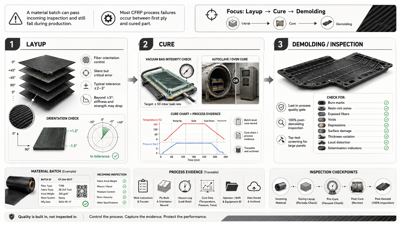
A material batch can pass incoming inspection and still fail in production.
The failure point often sits between the first ply going down and the part coming out of the autoclave or oven.
Most buyers never see this stage.
Fewer think to ask about it.
Three manufacturing stages carry most of the risk: layup, cure, and demolding. Each one needs defined records that a buyer can audit.
Layup and Preforming
Fiber orientation errors are silent failures.
For continuous-fiber CFRP, design tolerances often allow only ±2–3° of orientation deviation. Once deviation passes ±5°, laminate stiffness and strength can drop measurably.
That is the audit threshold.
At layup stage, buyers should ask for:
-
Ply-by-ply layup cards
-
Design angles such as 0° / ±45° / 90°
-
Operator sign-off
-
Timestamp after each layer
-
Defect checkboxes per ply
-
Corrective action log
-
Dual-confirmation sign-off for critical parts
For critical parts, one operator lays up the ply and a second checks the work against the ply sequence chart.
Defect checks should cover:
-
Bridging
-
Wrinkles
-
Gaps
-
Fiber distortion
-
FOD
-
Ply sequence error
-
Orientation error
-
Contamination
Gaps over 2–3 mm between fiber tows should be treated as rejection conditions unless the design allows them.
They can form void channels that grow under load.
Bridging at radii under 10 mm and wrinkles at curvature transitions should receive 100% visual inspection with photo documentation.
Spot checks are not enough for critical laminate features.
Cure Cycle Verification
Every autoclave or oven run should produce a full cure cycle chart.
A supplier that cannot provide a batch-level cure chart has already given you your answer.
Key cure parameters include:
|
Parameter |
Typical Requirement |
Deviation Risk |
|---|---|---|
|
Ramp rate |
2–5°C/min |
Too fast can cause outgassing or void clusters |
|
Hold temperature |
120–180°C, per spec |
More than 5–10°C low can cause under-cure or reduced Tg |
|
Hold time |
60–180 min |
More than 10–15% short can cause incomplete crosslinking |
|
Autoclave pressure |
0.5–0.7 MPa |
0.1–0.2 MPa low can increase porosity |
|
Vacuum level |
≥ −0.9 bar |
Any leak can drive porosity above 2–4 vol% |
Vacuum bag integrity needs its own checkpoint.
A practical leak-test rule is:
-
Pull vacuum to target level
-
Hold for 10–15 minutes
-
Confirm pressure drop below 2–5 kPa
-
Record pressure, time, operator, and batch
-
Repeat after bagging and again before autoclave entry
-
Keep each run’s records separate
Calibration is non-negotiable.
Temperature sensors, pressure transducers, vacuum gauges, and timers should follow 6–12 month calibration cycles under ISO 9001 or ISO 17025 practices.
Ask to see current calibration certificates.
Check the expiry dates.
For multi-zone autoclaves, ask for a temperature uniformity test report. It should show a maximum variance of ≤±5°C across the working zone.
Production Checklist Parameter Example
For checklist-driven production, some cured CFRP workflows may define process controls like:
|
Control Item |
Example Requirement |
|---|---|
|
Cure temperature |
180°C ±3°C |
|
Cure pressure |
0.6–0.7 MPa |
|
Vacuum |
≥90% |
|
Dwell time |
120 min ±10 min |
|
Cure record |
Full chart recorded per run |
|
Alarm status |
No open alarms |
These numbers must always be aligned with the material supplier’s cure cycle and the buyer’s specification. The point is not to copy a generic cure profile. The point is to make the profile measurable, auditable, and batch-linked.
Post-Cure Demolding
Demolding is where hidden process failures show up or get missed completely.
That happens when no one checks in a structured way.
Ask for 100% post-demolding inspection covering:
-
Burn marks
-
Resin-rich zones
-
Exposed fibers
-
Voids
-
Depressions
-
Surface damage
-
Thickness
-
Local distortion
-
Delamination indicators
-
Tap-test screening for large panels
Critical thickness should generally fall within ±0.2–0.5 mm of the design value unless a tighter tolerance is specified.
Thickness deviation can indicate cure quality, fiber volume fraction, resin content, cure pressure, compaction, or layup error.
Any part outside tolerance should go straight to quarantine.
The disposition record should define:
-
Use-as-is
-
Rework
-
Scrap
-
Concession
-
Responsible approver
-
Corrective action
-
Closure date
A verbal call on the shop floor is not acceptable for production-quality CFRP.
Minimum process control audit requirements:
|
Stage |
What to Request |
|---|---|
|
Layup |
Ply-by-ply cards, defect checklists, dual sign-off on critical parts |
|
Cure cycle |
Full autoclave or oven chart per batch, vacuum leak test records, calibration certificates |
|
Demolding |
100% inspection log, thickness data, MRB disposition with named approver |
Finished Part Inspection Standards: Dimensional, Visual, and Mechanical Testing
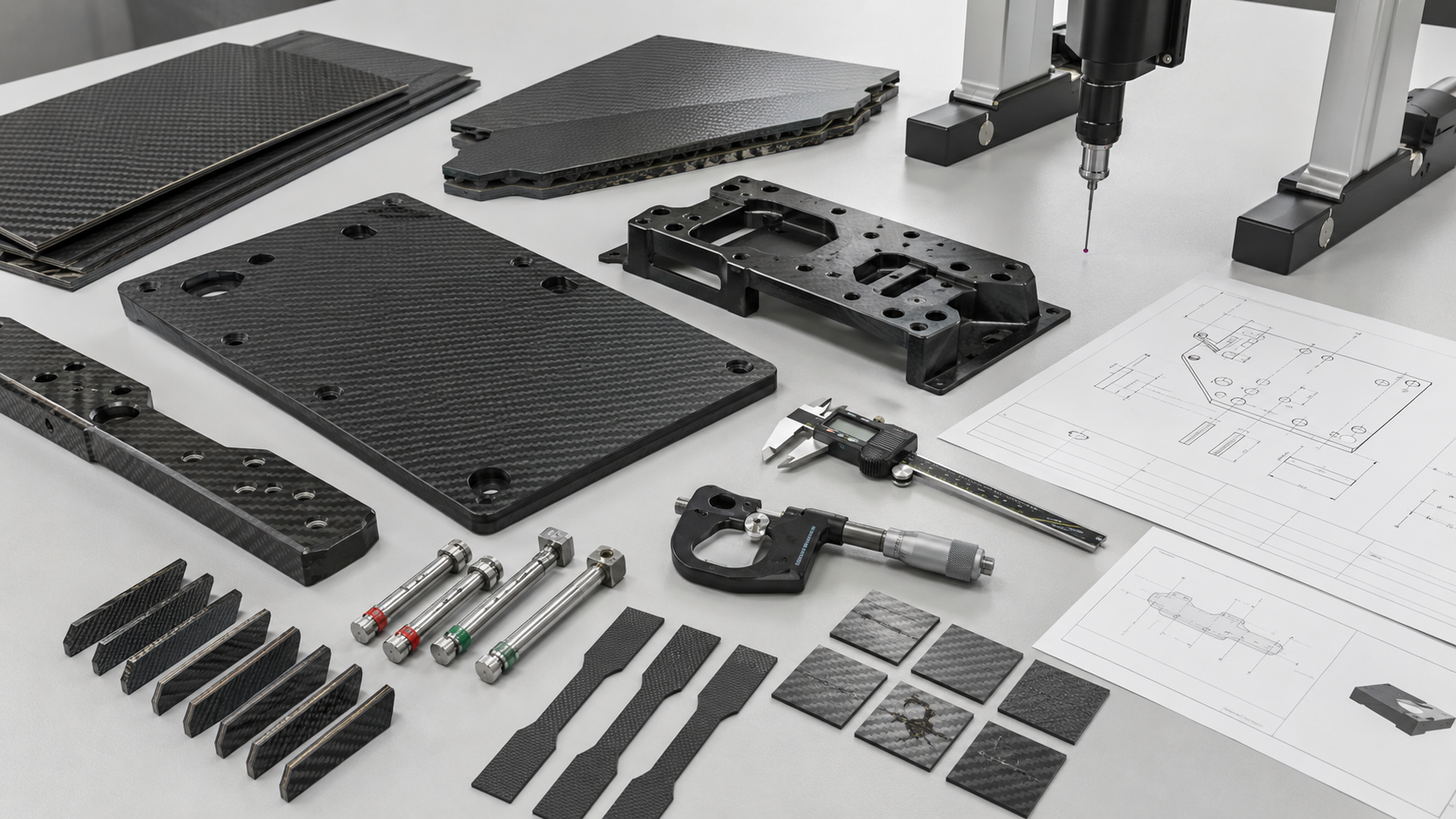
A finished carbon fiber part can clear process control and still fail final inspection.
Dimensions drift.
Surface defects hide in plain sight.
Mechanical properties can fall short of spec with no visible warning.
To catch these failures before shipment, buyers need three separate inspection passes: dimensional, visual, and mechanical. Each one needs defined acceptance thresholds.
Dimensional Inspection
Start with the critical-to-quality dimensions from the drawing or CAD model.
Typical CTQ features include:
-
Thickness
-
Hole diameter
-
Hole position
-
Flatness
-
Angularity
-
Datum surfaces
-
Interface features
-
Bonding areas
-
Trimmed edge geometry
Set a pass/fail rule for every critical feature before inspection begins.
Instrument selection should match the tolerance:
|
Feature Type |
Recommended Inspection Tool |
|---|---|
|
General dimensions |
Calipers, micrometers, plug gauges |
|
GD&T and tight tolerance |
CMM or optical comparator |
|
Flatness on structural panels |
Granite surface plate, feeler gauge, or CMM contour scan |
|
Complex surface |
3D scan or CMM scan |
Typical acceptance windows for CFRP finished parts include:
-
Thickness: ±0.2–0.5 mm for laminated panels, tighter for machined interfaces
-
Flatness: ≤0.05 mm for sealing surfaces
-
Aerospace structural flatness: often ≤0.02 mm
-
Hole diameter: ±0.01–0.05 mm
-
Bearing-fit holes: IT6–IT7 where specified
Every measurement should be logged.
Records should include:
-
Nominal value
-
Actual value
-
Tolerance band
-
Pass/fail result
-
Part number
-
Revision
-
Batch
-
Operator
-
Equipment ID
-
Inspection date
No actual value means no dimensional record.
Visual Inspection
Visual inspection needs defined thresholds.
No written acceptance criteria means visual inspection becomes guesswork.
For CFRP structural parts, hard rejection conditions include:
-
Any visible crack or fiber fracture on a structural surface
-
Resin-rich or dry-fiber patches exceeding 100 mm² in load-bearing areas
-
Surface voids larger than 0.5 mm in critical zones
-
Surface void area sum above 1% of a critical zone
-
Edge delamination visible to the naked eye at any ply interface
Conditional acceptance may apply only to non-critical surfaces, such as:
-
Minor scratches under 5 mm length and 0.02 mm depth
-
Localized resin waviness under 0.2 mm depth
-
Non-functional cosmetic variation within agreed surface class
Use a loupe or digital microscope when the surface call matters.
Photograph every defect.
Record type, location, size, zone, and disposition.
“Looks fine” is not an inspection record.
Mechanical Testing
Mechanical verification should follow a sampling plan tied to production volume and risk level.
For first article or new tooling, use:
-
100% dimensional inspection
-
Full mechanical qualification
-
Tensile testing
-
Compression testing
-
Flexural testing
-
ILSS testing
-
First Article Inspection Report
-
ISIR where required
-
PPAP with Cpk data and Part Submission Warrant where automotive customers require it
For serial production, a practical sampling baseline is:
-
3–5 coupon specimens minimum per batch for tensile testing
-
3–5 coupon specimens minimum per batch for ILSS testing
-
ASTM D3039 for tensile
-
ASTM D2344 for ILSS
-
ASTM D7264 for flexural, where required
A single specimen below the specified minimum should trigger batch review.
Adjust sampling intensity based on performance.
Tighten sampling when first-pass yield drops.
Ease it only when process stability is confirmed.
First-pass yield should be tracked by supplier and batch:
|
FPY Range |
Supplier Rating |
Required Action |
|---|---|---|
|
≥99% |
A-grade |
Standard cadence |
|
97–99% |
B-grade |
Increased surveillance |
|
<97% |
C-grade |
8D report and corrective action plan |
Track FPY per batch, per supplier, and per quarter.
Suppliers who hold high FPY earn longer commitments. Suppliers with repeated failures need corrective action plans or replacement.
A supplier who cannot provide batch-level inspection results should not be treated as production-ready for high-risk carbon fiber parts.
Non-Destructive Testing for CFRP: Choosing the Right Method
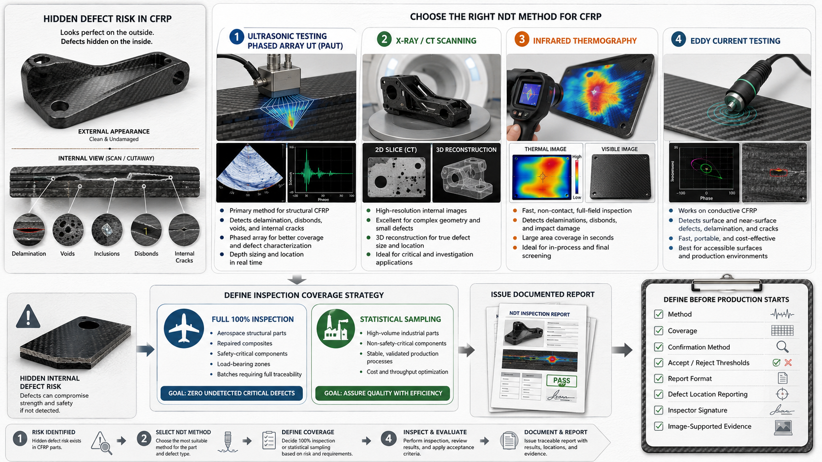
Many CFRP defects are internal.
A part can look clean and still contain delamination, voids, inclusions, disbonds, or internal cracks.
Pick the wrong NDT method and you may get a clean report on a part that is already failing.
That is why NDT should be defined before production starts.
Four methods dominate CFRP NDT:
-
Ultrasonic testing and phased array UT
-
X-ray and CT scanning
-
Infrared thermography
-
Eddy current testing
Each sees something the others miss.
Ultrasonic Testing and Phased Array UT
UT and PAUT are primary methods for structural CFRP.
They detect:
-
Delamination
-
Internal cracks
-
Porosity
-
Disbonds
-
Inclusions
Standard UT frequencies are often 2.25 MHz and below. For laminates thicker than 12.5 mm, lower frequencies such as 0.5 MHz may be used.
UT is a strong production method when internal defect sizing and location matter.
For delamination screening, ultrasonic C-scan can resolve defects down to 0.5–1 mm on laminates from 2–50 mm thick, depending on material, thickness, equipment, and setup.
Set scan step at no more than half the minimum detectable diameter.
PAUT can push detection probability above 90% on complex geometries when setup, calibration, and operator skill are controlled.
X-Ray and CT Scanning
CT scanning gives high-resolution internal images and 3D reconstruction.
It is useful for:
-
High-value small parts
-
Failure analysis
-
First article validation
-
Process validation
-
Confirming UT indications
-
Complex internal defect mapping
-
Direct void size and distribution analysis
CT scanning can provide void and inclusion detail at 10–50 μm resolution, depending on part size, wall thickness, and equipment capability.
CT is powerful but usually not the fastest production-line method.
Use it to confirm what UT flagged or to qualify a first article.
Infrared Thermography
Thermography gives fast, non-contact, full-field inspection.
It detects:
-
Delamination
-
Disbonds
-
Localized surface damage
-
Large-area panel defects
It is useful as a first-pass screen on large panels, followed by UT or CT on flagged zones.
Thermography works especially well on thin panels and honeycomb sandwich structures under 5 mm thick, where thermal contrast can reveal near-surface defects quickly.
Eddy Current Testing
ECT works on conductive CFRP.
It is useful for surface and near-surface defects. Pulsed ECT can extend depth capability and improve signal clarity.
ECT is not a universal replacement for UT or CT, but it can be valuable for fast screening of conductive CFRP surfaces.
A practical method-selection map is:
|
Defect |
Preferred Method Priority |
|---|---|
|
Delamination |
UT / PAUT → Thermography → CT → ECT |
|
Porosity |
CT → UT / PAUT → Thermography |
|
Inclusions |
CT → UT / PAUT → Thermography |
|
Surface or near-surface conductive defects |
ECT / PECT |
Full 100% inspection is appropriate for:
-
Aerospace structural parts
-
Repaired composites
-
Safety-critical components
-
Load-bearing zones
-
Batches requiring full traceability
Statistical sampling can fit:
-
High-volume industrial parts
-
Non-safety-critical components
-
Stable validated production processes
A common approach is to use thermography for rapid screening, then use UT or CT to follow up on flagged areas.
What to Write Into the Contract
Vague NDT clauses lead to disputes.
Specific ones stop them before they start.
The contract should specify:
-
Method
-
Coverage
-
Confirmation method
-
Accept/reject thresholds
-
Report format
-
Defect location reporting
-
Defect size reporting
-
Inspector signature
-
Image-supported evidence where required
A useful clause is:
Supplier shall perform 100% NDT on load-bearing zones using UT/PAUT as the primary method. CT shall confirm any suspect indications. Reports shall document defect type, location, dimensions, and disposition in image-supported format.
Common Carbon Fiber Defects Buyers Must Screen For
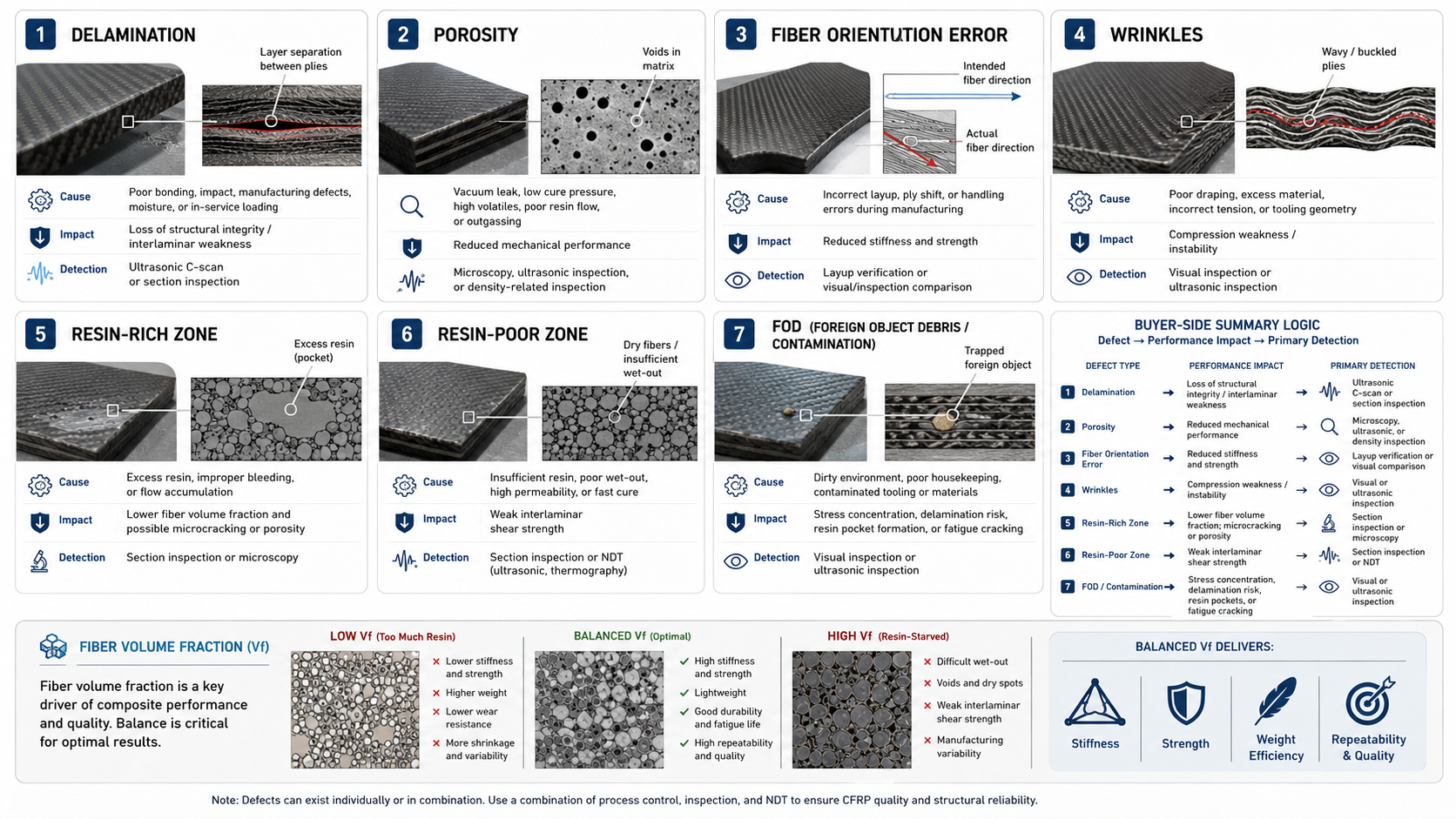
Seven defect categories cause most CFRP quality failures.
Each defect has a different cause, performance impact, and detection method.
Each one also has a threshold where a part moves from marginal to dangerous.
Know both before signing off on a batch.
Delamination
Delamination is layer separation.
It may come from poor resin flow, contamination between plies, impact, machining damage, poor drilling, weak compaction, or cure problems.
In aerospace structures, delamination over 6 mm equivalent diameter in a load-bearing zone usually requires evaluation or repair.
Location is critical.
A delamination in a high-stress region can reduce compressive strength by 40%+ and accelerate fatigue damage along the interface.
Detection methods include:
-
Ultrasonic C-scan
-
PAUT
-
Thermography for thin panels and sandwich structures
-
CT confirmation where required
Porosity and Voids
Porosity comes from vacuum leaks, low cure pressure, high volatiles, poor resin flow, or outgassing.
Aerospace-grade CFRP often requires ≤1–2% void volume fraction.
Automotive structural parts may allow ≤3–5%.
The numbers get serious fast.
Porosity above 5% can reduce interlaminar shear strength by 20–30%.
Detection methods include:
-
UT attenuation
-
CT scanning
-
Density comparison against theoretical fiber-volume-fraction values
-
Microscopy where required
Flag any batch where ultrasonic attenuation jumps more than 20–30% above the qualified baseline.
Fiber Misalignment
Fiber orientation error reduces stiffness and strength.
Deviation beyond ±2–3° should be controlled carefully. Once deviation passes 5–10°, axial stiffness and strength can fall by 10–30%.
High-performance structures may require control down to ±1°.
For AFP processes, gaps should stay under 1–2 mm. Overlaps should stay under 2–3 mm.
Detection methods include:
-
In-line machine vision
-
AI-based optical systems
-
Ultrasonic anisotropy analysis
-
Layup inspection records
Wrinkles
Wrinkles are especially damaging in compression-dominated structures.
In-plane wrinkles can cut compression strength by 30–60% in the primary load direction.
The key measurement is wrinkle height-to-wavelength ratio. A higher ratio means higher compression failure risk.
Detection methods include:
-
PAUT
-
C-scan
-
Structured-light 3D scanning
-
In-process vision systems
Resin-Rich and Resin-Poor Zones
Resin-rich and resin-poor zones both hurt performance.
They fail through different paths.
Resin-rich zones lower fiber volume fraction, add porosity, and create microcracking risk.
Resin-poor zones leave dry fiber with weak interlaminar shear capacity.
Detection methods include:
-
X-ray density mapping
-
Ultrasonic reflection contrast
-
Burn-off sampling for local fiber volume fraction
Foreign Object Debris and Inclusions
FOD can create stress concentrations, delamination, resin pockets, or fatigue cracks.
Hard FOD includes metal chips or fasteners.
Soft FOD includes backing film, tape, paper, cloth, or packaging debris.
Both are preventable.
Controls include:
-
ISO Class 8 or better air cleanliness in open layup areas
-
100% pre-ply visual inspection
-
White light and raking illumination
-
X-ray for dense inclusions
-
AI optical monitoring where available
Fiber Volume Fraction Inconsistency
Fiber volume fraction controls stiffness, strength, weight, and repeatability.
Aerospace structures often target 55–65% FVF.
Automotive and sporting goods parts may run 45–60%.
Batch-to-batch variation should stay within ±2–3%.
Dropping FVF from 60% to 50% can reduce axial modulus by 15–20% because of rule-of-mixtures behavior.
Burn-off testing is a standard batch gate for FVF verification.
A buyer-side defect summary can look like this:
|
Defect |
Performance Impact |
Primary Detection Method |
|---|---|---|
|
Delamination |
Compressive strength −10–60% |
UT C-scan / PAUT |
|
Porosity >5% |
ILSS −20–30% |
UT attenuation / CT |
|
Fiber misalignment >5° |
Axial strength −10–30% |
Machine vision / PAUT |
|
Wrinkles |
Compression strength −30–60% |
PAUT / 3D scan |
|
Resin-poor zones |
Severe ILSS loss |
X-ray / burn-off sampling |
|
Hard FOD |
Fatigue life reduction |
X-ray / visual |
|
FVF deviation ±5% |
Modulus −15–20% |
Burn-off test |
Pre-Production Quality Control Checklist for Carbon Fiber Buyers
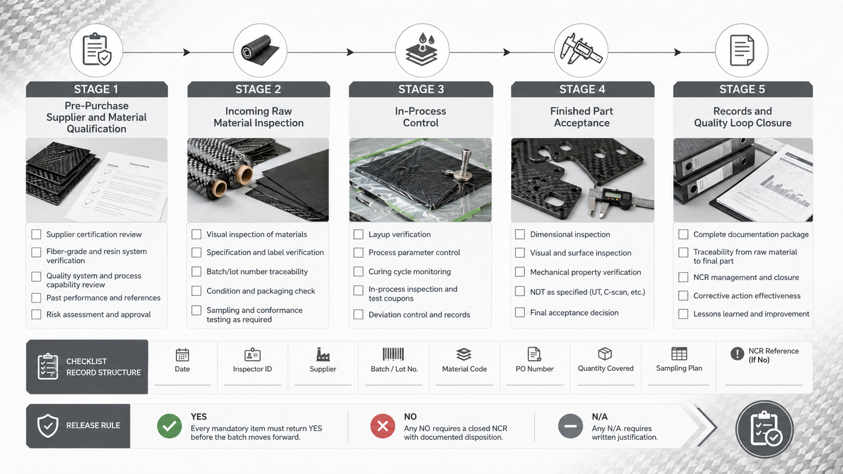
This guide leads to one practical tool: a structured checklist used before production starts.
Five stages.
One document.
No gaps.
Each item should follow this record structure:
Stage → Checkpoint → Requirement and Method → Record: Yes / No / N/A
For every item, log:
-
Date
-
Inspector ID
-
Supplier name
-
Batch or lot number
-
Material code
-
PO number
-
Quantity covered
-
Sampling plan, such as AQL level
-
Nonconformance reference when the answer is No
A single No without a closed NCR is a hold, not a pass.
Stage 1: Pre-Purchase Supplier and Material Qualification
|
# |
Checkpoint |
Requirement and Method |
Record |
|---|---|---|---|
|
1.1 |
Supplier certification validity |
ISO 9001 / AS9100 / IATF 16949 certificate copy on file; expiry more than 6 months remaining where possible; scope covers the specific product and process |
Yes / No / N/A |
|
1.2 |
NADCAP composites approval |
Required for aerospace applications where specified; confirm status in the NADCAP database |
Yes / No / N/A |
|
1.3 |
Fiber grade and specification confirmation |
Grade such as T300 / T700 / IM7 / T800; tensile strength ≥3.5 GPa where specified; modulus ≥230 GPa where specified; filament count such as 3K / 6K / 12K / 24K; sizing chemistry and content 0.5–2.0 wt%; attach spec sheet with min/max limits and test methods such as ASTM D4018 / ISO 13002 |
Yes / No / N/A |
|
1.4 |
Shelf life and storage requirements |
Shelf life stated on documentation, often 12–24 months for PAN fiber; storage ≤25°C, ≤60% RH; sealed packaging with desiccant |
Yes / No / N/A |
|
1.5 |
FAI / qualification sample plan |
Run 3–5 trial lots minimum where required; test matrix covers fiber tensile, sizing content, laminate void content below 1–2%, cured Tg, and fiber areal weight; acceptance criteria locked before production begins |
Yes / No / N/A |
|
1.6 |
AQL and deviation process |
AQL level stated in contract; AQL 1.0–1.5 for major defects; AQL 0.25 for critical defects; MRB / NCR / waiver process defined |
Yes / No / N/A |
Stage 2: Incoming Receipt and Raw Material Inspection
|
# |
Checkpoint |
Requirement and Method |
Record |
|---|---|---|---|
|
2.1 |
Package quantity vs. PO |
Count vs. PO; maximum discrepancy ±0.5%; flag any shortfall immediately |
Yes / No / N/A |
|
2.2 |
Package marking and identification |
Material code, lot or batch number, production date, weight within ±2% vs. label, manufacturer, and specification revision confirmed per package |
Yes / No / N/A |
|
2.3 |
Visual inspection of fiber rolls or tows |
No frayed edges, broken filaments, contamination, moisture marks, oil stains, or crushed cores; use AQL-based sampling, such as 50 bobbins from a lot of 500 under ANSI Z1.4 Level II; 0 critical defects; ≤1 minor defect per roll |
Yes / No / N/A |
|
2.4 |
Dimensional spot checks |
Roll width within tolerance, such as 300 mm ±2 mm; fiber linear density within ±5% of spec using weigh-and-length method |
Yes / No / N/A |
|
2.5 |
Warehouse environment at receipt |
18–25°C, ≤60% RH; out-of-range condition means quarantine the lot and log the deviation |
Yes / No / N/A |
|
2.6 |
CoA / CoC documentation |
CoA present for each lot; tensile strength, modulus, sizing percentage, density, and filament count checked against internal spec; lot barcode entered into warehouse system |
Yes / No / N/A |
Stage 3: In-Process Control: Layup, Winding, and Cure
|
# |
Checkpoint |
Requirement and Method |
Record |
|---|---|---|---|
|
3.1 |
Fiber tension control |
Tension within set range, such as 5–20 N depending on tow size; variation ≤±10%; auto-log every 30 minutes; alarm threshold ±15% |
Yes / No / N/A |
|
3.2 |
Equipment calibration status |
Critical instruments such as tension sensors, thermocouples, pressure gauges, and resin scales current on calibration date; 6–12 month calibration cycle; certificates on file |
Yes / No / N/A |
|
3.3 |
Cure cycle verification per batch |
Temperature 180°C ±3°C where specified; pressure 0.6–0.7 MPa where specified; vacuum ≥90%; dwell time 120 min ±10 min; full chart recorded per run; no open alarms |
Yes / No / N/A |
|
3.4 |
Material identity and lot control |
Fiber grade matches traveler or route card; mixed lots require MRB authorization; lot map kept per part |
Yes / No / N/A |
|
3.5 |
In-process defect checks |
Visual checks every 10 parts or every 2 hours; check bridging, wrinkles, gaps, and FOD; 100% visual inspection for aerospace where required; document all rework |
Yes / No / N/A |
|
3.6 |
NCR / MRB for deviations |
Log each deviation with NCR ID, part ID, lot, defect type, location, and detection stage; record and close MRB disposition as rework, use-as-is, scrap, or concession |
Yes / No / N/A |
Stage 4: Finished Part Acceptance
|
# |
Checkpoint |
Requirement and Method |
Record |
|---|---|---|---|
|
4.1 |
Dimensional inspection |
Key dimensions vs. drawing; ±0.1–0.5 mm for precision parts where specified; record actual values per feature |
Yes / No / N/A |
|
4.2 |
Part weight check |
Actual weight vs. theoretical; deviation ≤±2–3%; flag outliers as possible void or excess-resin signs |
Yes / No / N/A |
|
4.3 |
Mechanical coupon testing |
Run tensile ASTM D3039, flexural ASTM D7264, and ILSS ASTM D2344 per batch where required; tensile must reach ≥design allowable ×0.95; modulus within ±5%; ILSS above spec minimum |
Yes / No / N/A |
|
4.4 |
Void content or porosity |
Measure via CT, density comparison, or microscopy; ≤1–2% for aerospace structural parts; ≤3–5% for automotive structural parts |
Yes / No / N/A |
|
4.5 |
Surface and visual defects |
Check for pinholes, fiber print-through, resin-rich or resin-poor zones, delamination, and impact marks; 0 critical defects; ≤3 minor defects per m²; no continuous defect over 10 mm |
Yes / No / N/A |
|
4.6 |
NDT inspection |
Method such as PAUT / CT / thermography per contract; cover 100% of load-bearing zones or use AQL sampling; defect limits per drawing; image-supported report on file |
Yes / No / N/A |
|
4.7 |
Sampling plan compliance |
Safety-critical parts require 100% inspection; industrial parts may use AQL 0.65–1.5 for major defects; confirm sample size per table |
Yes / No / N/A |
|
4.8 |
Documentation and release |
FAI report, batch inspection report, CoA, cure cycle charts, and material lot map complete; QA release signature obtained; any open No equals hold |
Yes / No / N/A |
Stage 5: Records and Quality Loop Closure
|
# |
Checkpoint |
Requirement and Method |
Record |
|---|---|---|---|
|
5.1 |
Record retention |
Aerospace: 10–15 years minimum where required; industrial: 5 years; files cover CoA, warehouse logs, calibration certificates, cure data, inspection results, and NCR / MRB decisions |
Yes / No / N/A |
|
5.2 |
Trend analysis and KPI review |
Run at least quarterly; track incoming rejection rate target under 1% of lots, in-process scrap target under 2%, and on-time delivery with zero concessions target at or above 95%; share findings with supplier and process owners |
Yes / No / N/A |
The release rule is direct:
Every mandatory item must return Yes before the batch moves forward. Any No requires a closed NCR with documented disposition. Any N/A requires written justification on file.
Run the checklist once and it may feel like overhead.
Run it on every batch and it becomes the system that stops bad material from turning into field failures.
What Buyers Should Send Before Production Starts
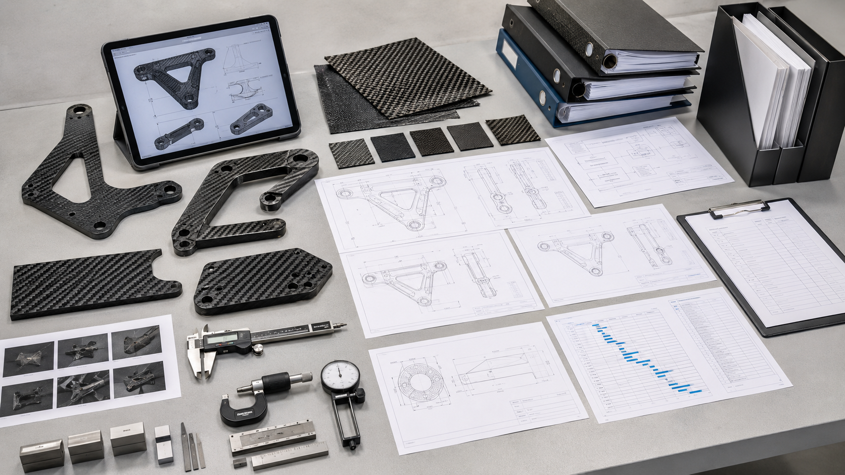
Quality control works best when the buyer defines requirements before the supplier starts quoting, ordering materials, cutting plies, or building fixtures.
Before production starts, send the supplier:
-
3D CAD file
-
2D drawing
-
Part number and revision
-
Critical dimensions
-
Surface class
-
Tolerance requirements
-
Load direction
-
Material expectation
-
Fiber grade, if specified
-
Resin system, if specified
-
Prepreg or dry-fiber preference
-
Mechanical property targets
-
NDT requirements
-
Visual acceptance standard
-
Documentation requirements
-
Traceability level
-
Quantity target
-
First article requirement
-
Pilot batch requirement
-
Production ramp plan
For structural or safety-related parts, also define:
-
Load case
-
Failure mode concerns
-
Environmental exposure
-
Temperature range
-
Fatigue requirement
-
Impact requirement
-
Bonding or fastening method
-
Required coupon test plan
-
Required inspection report format
-
Retention period for records
At HyperX Carbon, buyer information is reviewed before final quotation whenever quality risk affects cost, tooling, process route, inspection, or documentation.
If a drawing does not define surface class, tolerance, NDT, material grade, or traceability, we clarify those items before locking the production plan.
A strong quality plan starts with a complete production input package.
Work with HyperX Carbon on Quality-Controlled Carbon Fiber Production
Carbon fiber does not forgive shortcuts.
Neither does production.
A defect found in a finished part means the project has already paid part of the real price. The cost may appear as scrap, delay, rework, failed testing, customer claims, assembly problems, damaged client relationships, or lost confidence in the supplier.
Most carbon fiber quality failures are preventable when buyers and manufacturers define the right controls before production.
The right system includes:
-
Clear material specification
-
Supplier qualification
-
Incoming material inspection
-
Layup and cure records
-
Finished part inspection
-
NDT where required
-
Defect screening
-
Batch traceability
-
NCR and MRB closure
-
Final release documentation
HyperX Carbon supports carbon fiber quality review before production for custom parts, CNC-machined plates, molded components, visible carbon parts, UAV structures, automotive components, industrial brackets, and application-specific CFRP projects.
Send us your CAD file, 2D drawing, material requirement, tolerance requirement, quantity target, application, quality expectation, inspection requirement, and timeline.
We can review the production route, identify quality-control risks, and recommend a practical inspection plan before quotation or production begins.
A better carbon fiber project does not start with final inspection.
It starts with quality control before production.