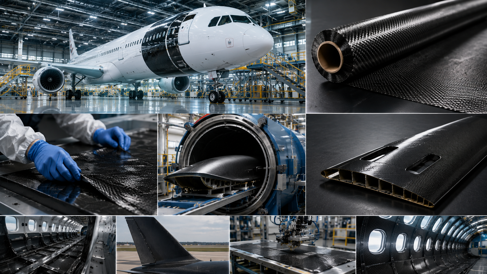
Carbon fiber prepreg sits at the intersection of materials science and precision manufacturing. Yet for most engineers and buyers seeing it for the first time, the actual process of making it stays opaque. You know the end result: a resin-saturated fiber system with tight process control that delivers exceptional strength-to-weight performance in aerospace cabins, racing chassis, and high-end sporting equipment. But how does raw carbon fiber and liquid epoxy become that cool, tacky, engineered sheet sitting in a cold storage freezer?
That transformation involves more steps, more variables, and more deliberate engineering than most people expect. The process spans several distinct stages:
-
Fiber creel setup and tension control
-
Resin film coating and impregnation
-
B-stage curing
-
Cold-chain storage
-
Final part consolidation
This guide walks through each stage of the prepreg carbon fiber manufacturing process. You’ll get the technical clarity to evaluate materials, ask sharper supplier questions, and make better production decisions.
Key Raw Materials Used in Prepreg Manufacturing
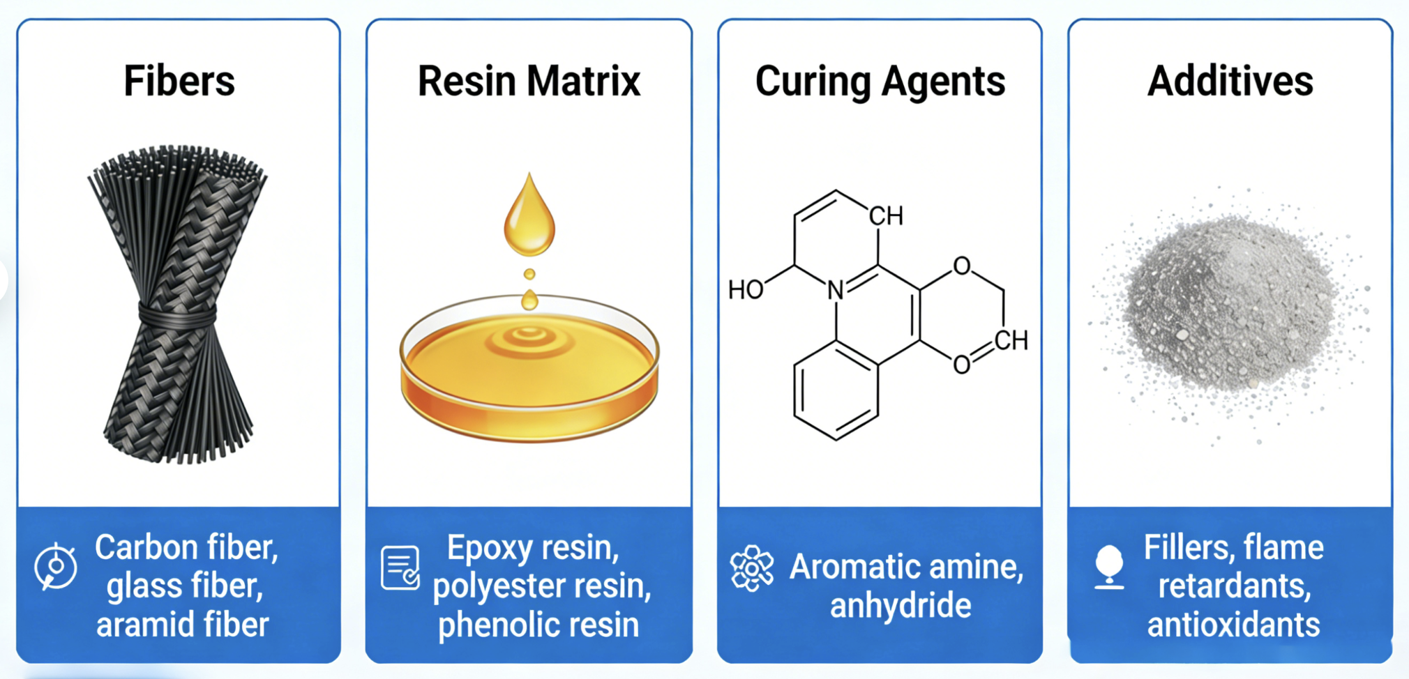
Every prepreg sheet starts with two inputs. Get either one wrong, and no downstream process control saves the part.
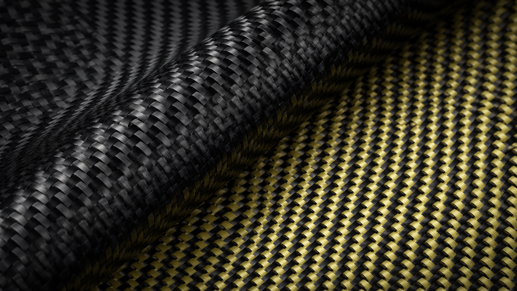
Carbon fiber makes up 58–69% of the total prepreg by weight. It comes in three modulus grades — standard, intermediate, and high. Each grade carries a different price point: standard at $50–65/kg, intermediate at $65–75/kg, and high at $75–80/kg. Each also delivers a different stiffness-to-weight profile. Architecture matters too. Unidirectional tapes concentrate strength along a single axis. That makes them the go-to choice for primary structural loads. Woven fabrics — plain weave or twill — give up some mechanical efficiency in exchange for drapability. Twill also produces a surface finish that aerospace interiors and consumer products call out by name in their specs.
Resin fills the remaining 31–42%. Epoxy dominates, but the formulation is never generic. Engineers dial in glass transition temperature (Tg ranges span 120–200°C), toughener loading, and flow agents based on the end application.
Here’s how that breaks down by use case:
-
Engine-bay components need high-Tg systems to survive heat exposure
-
Impact-prone structures get toughened epoxies for better damage resistance
-
General structural parts use standard epoxy tuned to the cure cycle
The resin arrives pre-formulated and B-staged to a controlled viscosity. That single characteristic eliminates on-site mixing and locks the fiber-to-resin ratio before the material reaches a cutting table.
Step 1 — Fiber Preparation: Creel Setup and Tow Spreading

Before a single drop of resin touches the fiber, something quieter but just as critical happens. The carbon tow gets pulled, tensioned, and flattened into a thin sheet. That sheet needs to be uniform enough to accept even resin impregnation.
This is creel setup — and most process failures trace back to it.
Raw carbon fiber spools mount onto a creel rack. They feed through a tensioning system before reaching the spreading machine. Tension matters more than you’d think. Too loose, and filaments wander. Too tight, and they break. The right tension holds every filament parallel. That controls how well resin penetrates later.
What spreading does:
A 12K tow — 12,000 individual filaments — arrives bundled at about 5 mm wide. Mechanical rollers or controlled airflow push that bundle flat, expanding it to 25 mm. That’s an 80% reduction in thickness. The result: minimal gaps, reduced crimp, better resin flow paths.
UD vs. woven fiber prep diverge at this stage:
|
UD Prepreg |
Woven Prepreg |
|
|---|---|---|
|
Tow count |
12K+ spread tows |
1–6K tows |
|
Spreading emphasis |
Critical — tows must lie flat |
Lower priority |
|
Areal weight range |
Wider tapes, higher weights |
90–300 g/m² |
|
Fiber alignment |
Near-perfect parallelism |
Crimp present at crossovers |
For unidirectional prepreg, multiple spread tows move together across a machine sometimes 200 feet long. All of them advance at once into a single, aligned ply. Any tension mismatch between tows creates waviness. Waviness creates a mechanical weak point — it’s that direct.
Before the sheet moves to impregnation, a visual uniformity check runs through the whole width. No gaps. No crossovers. No misaligned tows.
Step 2 — Resin Film Preparation: Coating and Thickness Control

Resin doesn’t get poured onto fiber. It gets metered onto a release paper first — cast into a thin, uniform film before it ever touches a filament.
This is the hot-melt film coating process, and the physics here are unforgiving.
Molten epoxy feeds through a heated die onto a release carrier. Viscosity runs between 1,000–10,000 mPa·s throughout this step. A calibrated coating blade sets the gap. The substrate moves. Film thickness comes from that gap, that speed, and the fluid dynamics between them — what engineers call the capillary number relationship.
Get it wrong, and downstream problems stack up fast:
-
Film too thin — poor fiber wet-out, dry spots, adhesion failures in the final laminate
-
Film too thick — resin pooling, excess weight, inconsistent fiber volume fraction, cure anomalies
Target thickness falls between 10–600 μm, based on areal weight requirements. For standard structural prepreg at 35–42% resin content by weight, film weight tolerances hold at ±3 g/m². That’s a tight band. Every production run needs calibrated measurement to stay inside it.
Blade angle, gap height, and traverse speed all shape the final build. Even small inconsistencies create thickness gradients across the roll width. Those gradients look harmless on the film. In the cured part, they show up as mechanical property scatter — real, measurable variation that affects structural performance.
That’s why film coating runs as a controlled process, not an estimated one.
Step 3 — Fiber Impregnation: How Resin Penetrates Carbon Fibers

The resin film is ready. The fiber sheet is flat, tensioned, and aligned. Now the two become one.
Hot-melt impregnation is the standard method in commercial prepreg carbon fiber manufacturing. The resin film — cast in Step 2 — gets pressed against the spread fiber sheet. Both layers feed through a series of heated nip rollers. Heat lowers resin viscosity into a workable flow range. Mechanical pressure drives it into the tow structure. The result: full wet-out with no solvent, no mess, no guesswork.
The physics here are straightforward. Spreading the fiber tows in Step 1 increased surface area and reduced bundle thickness. Both changes boost capillary action — the same force that pulls liquid into a narrow gap. Molten resin follows that path, flowing between filaments as pressure presses the stack together.
The Roller Sequence That Controls Everything
No single roller handles this job. A multi-nip system moves the material through three distinct stages:
-
Impregnation rollers — push resin into the fiber under heat and pressure
-
Metering rollers — strip excess resin and spread it evenly across the full width
-
Calender rollers — final compression, locking in thickness and areal weight
This sequence holds resin content (RC%) between 30–45%. That range matches a fiber volume fraction of 50–70% in the finished laminate. Step outside that window in either direction and problems build fast.
Dry spots form when viscosity runs too high, spreading is uneven, or pressure falls short. Resin doesn’t reach the fiber core. In a cured part, those voids act as stress points — invisible until something breaks.
Resin-rich zones go the other way. Over-application or a badly set metering gap leaves excess resin pooled between plies. That adds weight, throws off fiber volume fraction, and creates uneven mechanical properties across the laminate.
Both failure modes are preventable. Precise temperature control keeps viscosity on track. Metering rollers pull out surplus before it sets. Real-time sensors track thickness and RC% non-stop — catching drift before it reaches the winding stage.
Step 4 — B-Stage Partial Curing: Achieving the Right Degree of Cure
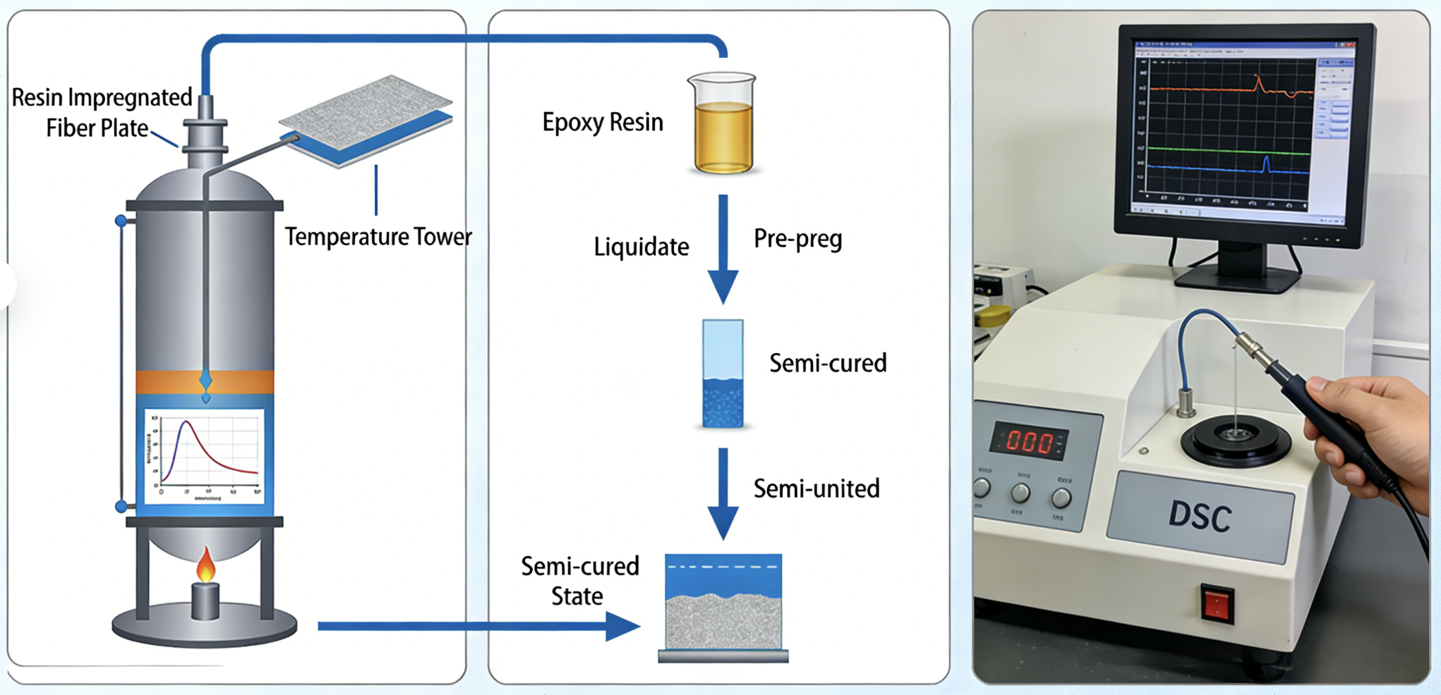
Cured epoxy is useless for layup. So is liquid epoxy. B-staging sits deliberately between those two states — and hitting that middle point is what makes prepreg prepreg.
After impregnation, the resin-saturated fiber sheet moves through a temperature-controlled tower. Heated zones push the epoxy out of its A-stage liquid form and into a B-stage solid — one that’s only part-way crosslinked. The target: 20–40% degree of cure (DOC). Not 15%. Not 45%. That window is tight on purpose.
The chemistry behind this is chain extension. Resin molecules bond together, viscosity rises, and the glass transition temperature (Tg) climbs just above room temperature. What you get is that familiar tacky, gel-like sheet. Firm enough to handle. Flexible enough to drape over complex tooling shapes.
DOC is measurable, not estimated:
DOC = 1 − (ΔH_residual ÷ ΔH_total)
Take a standard epoxy with a total heat of reaction around 320 J/g. A residual of 79 J/g puts DOC near the optimal range. DSC is the go-to measurement tool. Raman spectroscopy and dielectric analysis (DEA) track the same cure progression under steady-temperature conditions.
What Happens When the DOC Misses the Window
The failure modes at each extreme are distinct — and both damage the final part.
|
Condition |
DOC |
Consequence |
|---|---|---|
|
Under-cured |
< 20% |
Too liquid, excessive flow during cure, high void content |
|
Optimal |
20–40% |
Tacky, handleable, controlled flow, low voids |
|
Over-cured |
> 40–50% |
Brittle, low tack, poor drape, restricted flow, elevated porosity |
Resin chemistry moves the tolerance band. Low-temperature epoxies B-stage between 40–80°C. Their reaction speed is faster, so the process window is tighter and temperature-time control leaves less margin for error. High-temperature systems run between 80–120°C. Chain extension is slower there, so manufacturers get more room to stay within spec.
Once the DOC lands in the target zone, the sheet cools right away. Crosslinking stops. The out-time clock starts.
Step 5 — Cooling, Slitting, and Winding into Final Form
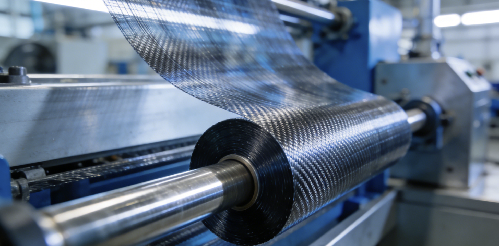
The B-staged sheet exits the curing tower warm, tacky, and reactive. Leave it that way and it sticks to itself. Three operations follow — cooling, slitting, winding — and each one stops that from happening.
Cooling happens fast, but with precision. The sheet runs over a series of water-cooled rollers. Each roller holds within a set temperature band. A dual-roller gradient setup runs the first roller at 30–35°C and the second at 25–30°C. Surface temperature must reach ≤35°C before winding — any warmer and the layers start bonding together. Auxiliary wind knives blow 15–20°C compressed air across the surface. This drops surface temperature by another 5–10°C and pushes the overall cooling rate up by 20–30%.
Slitting converts wide rolls into usable widths. For AFP and ATL machines, the standard output is 6.35mm or 12.7mm narrow tape. Servo-driven circular or flat blades keep tolerances tight. Some applications call for ±0.05mm consistency. Carbon fiber slitting lines need enclosed protective covers. Conductive fiber particles near exposed electrical sources create a real fire risk — no exceptions.
Winding locks in all the precision built up before this point. Closed-loop tension control uses strain gauge or floating-roller feedback to adjust torque in real time. Taper tension lowers the winding force as roll diameter grows. This protects inner layers from compression. Final spools ship on 76mm (3-inch) air-expanding shafts, ready to load straight into automated placement machines.
Quality Control: How Manufacturers Ensure Prepreg Consistency
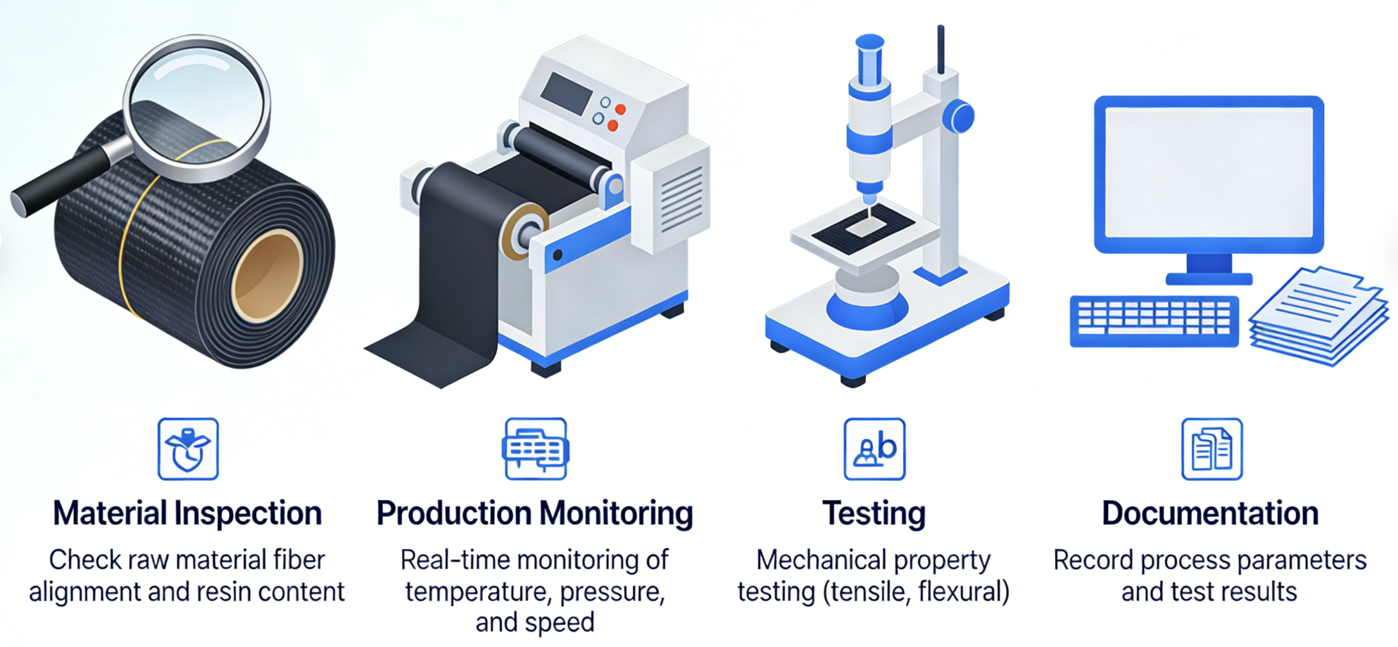
Consistency is the whole game. Every process step — fiber spreading, resin film casting, B-staging, winding — delivers value if the final roll meets spec. QC confirms that it did.
Manufacturers run several interconnected checks:
Resin content gets confirmed through a burn-off test or thermogravimetric analysis (TGA). Strip the fiber. Weigh what’s left. That number targets 35–45% by weight. It drives fiber volume fraction, resin flow behavior, and final mechanical performance.
Thickness uniformity gets checked through ultrasonic C-scan. This method catches dry spots and resin-rich zones early. You catch them before they turn into structural problems in a cured laminate.
Tack testing measures peel force — the “stickiness” that makes layup work. Tack drops with time and increases with temperature and humidity. Tracking it helps prevent layup failures. It also guides adjustments to cure parameters.
DSC tracks B-stage aging. Regular measurements confirm the cure level stays within the 20–40% window.
Aerospace programs add a stricter layer. NADCAP and AS9100 certification require full NDT coverage. They also require C-scan checks for voids and delaminations, plus documented traceability across every production lot. Automotive QC focuses more on resin impregnation and cure cycle consistency — less NDT intensity, more throughput discipline.
The payoff is real. Strong QC cuts scrap, reduces rework, and raises first-pass yield. Consistent resin flow from the factory means fewer surprises on the shop floor.
Prepreg Storage Requirements: Cold Chain and Shelf Life Management
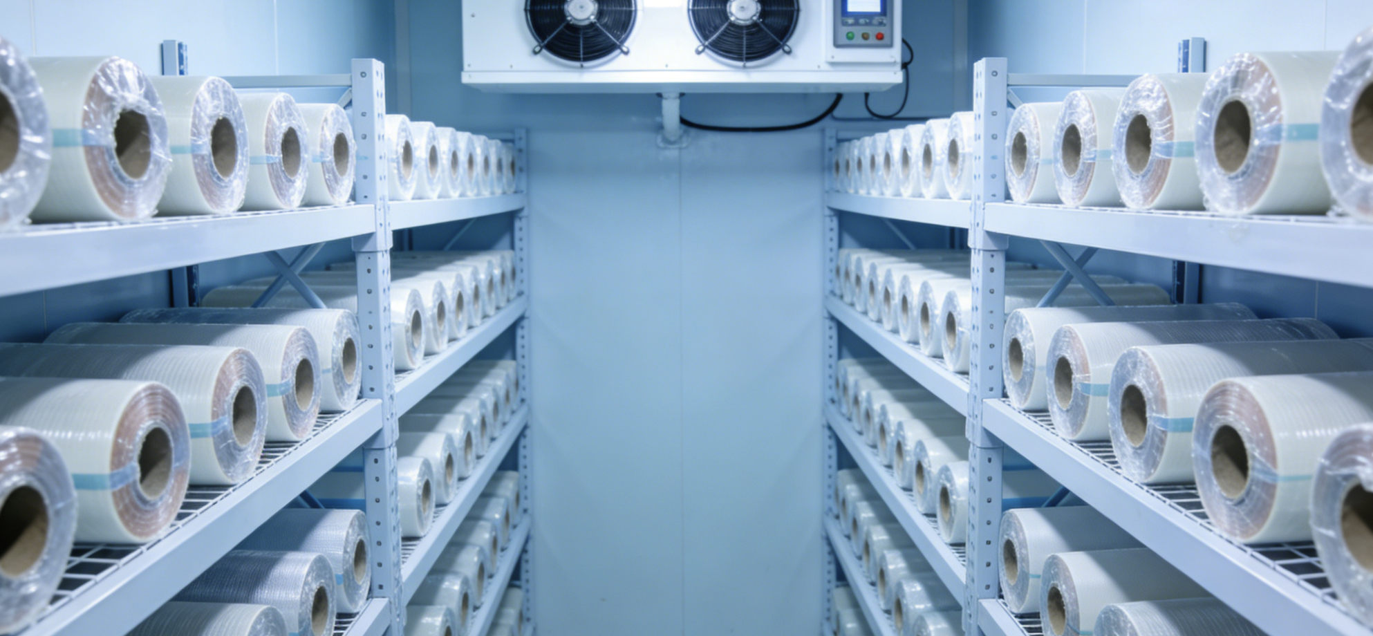
The cold chain isn’t a convenience — it’s the continuation of manufacturing by other means.
The B-stage clock starts the moment prepreg leaves the freezer. From that point, everything is a race against resin chemistry. At room temperature, crosslinking keeps moving. It’s a quiet, continuous reaction — and it can’t be undone. Freezer storage at −18°C to −22°C brings that reaction rate down to near-zero. This holds the resin’s flow behavior and Tg profile stable until the material hits the cutting table.
Shelf Life vs. Out-Time: Two Different Clocks
These terms get mixed up often. They mean different things.
-
Shelf life — the total usable time from manufacture, counted under frozen storage. Standard: 12–18 months at ≤−18°C
-
Out-time — the total room-temperature exposure time before the material can no longer be used. Window: minutes to 30 days, depending on resin system
Each hour at room temperature eats into out-time. That loss is permanent. There’s no way to reset it.
Thawing Protocol
Cut corners here and you get condensation. Condensation leads to delamination, measles defects, and a depressed Tg in the cured laminate. Follow every step.
-
Keep the roll sealed inside its moisture-proof polyethylene bag
-
Allow 24–48 hours to reach ambient temperature
-
Check temperature indicators before opening the bag
-
Run a vacuum desiccation step after thawing to pull out residual moisture
Got unused material? Evacuate the air, heat-seal the bag, and send it back to the freezer right away. Log the cumulative out-time on the packaging label — every session counts.
Degradation signs to watch: loss of tack, stiffness during handling, inconsistent resin flow at layup.
From Prepreg to Finished Part: Layup, Debulking, and Curing

The roll is thawed. The clock is running. Now the material has to become a part.
Layup starts with tool preparation — a release medium between mold and laminate. Plies go down with precise positioning. Every five layers or fewer, stop. Debulk.
Debulking: The Step Most Beginners Skip
Skip the debulk and you get bridging, wrinkles, and voids. The fix is simple:
-
Apply perforated release film, then breather cloth
-
Seal the assembly in a vacuum bag
-
Pull full vacuum for a minimum of 10 minutes
Do this after the first ply, then every 3–4 plies for thicker laminates. Complex shapes need more frequent debulk cycles. An overnight layup means an overnight debulk — no exceptions.
Cure Cycle Execution
Two-stage cure profiles are the standard approach. A typical OOA oven cure runs 70°C for 4 hours, then ramps to 120°C for 1 hour at 1.5–3°C/min. Thin-walled tools can need a 40°C dwell for 2 hours before the main ramp. This holds resin flow in check before gelation sets the matrix.
Let the part cool to room temperature before demolding. Pull it out too soon and surface defects are guaranteed.
Hot Melt vs. Wet Impregnation: Choosing the Right Manufacturing Method

Two methods dominate commercial prepreg carbon fiber production. Both make rolls that look the same. The results are not the same.
Hot-melt impregnation is the industry standard for structural prepreg. Resin heats until it flows, then presses into spread fiber tows through nip rollers — no solvents, no carrier fluids. The process is clean, fast, and repeatable. Resin content stays within spec. Fiber volume fraction stays predictable.
Wet impregnation works the opposite way. Fiber passes through a liquid resin bath, where resin is dissolved in solvent. After the fiber soaks through, the solvent evaporates. It sounds simple, but the real cost adds up fast. Residual solvents stay trapped in the cured matrix. Void content rises. Resin distribution gets harder to control at scale.
|
Factor |
Hot-Melt |
Wet Impregnation |
|---|---|---|
|
Solvent use |
None |
Organic solvents required |
|
Resin consistency |
Tight tolerance |
Concentration-dependent variation |
|
Void risk |
Low |
Higher |
|
Scalability |
High |
Limited |
For structural carbon prepreg production, hot-melt wins on every metric that matters.
Unidirectional vs. Woven Carbon Fiber Prepreg: Manufacturing Differences

The fiber architecture choice happens before resin ever enters the process. That one decision shapes everything that follows.
Unidirectional (UD) prepreg locks all fibers parallel at 0°. Tows lie flat and nested tight against each other. Resin fills a compact, uniform structure with no weave gaps to bridge. That geometry means lower resin content, faster impregnation, and a production cost 3–4× lower than woven alternatives.
Woven prepreg — twill is the most common — crosses fibers at 90° in an over-under interlace. Those crossover points create small voids. More resin fills them. The weaving step also adds time and cost on top of that.
The performance tradeoff is clear:
|
Property |
UD Prepreg |
Woven Prepreg |
|---|---|---|
|
Primary stiffness (E1) |
120 GPa |
56 GPa |
|
Transverse stiffness (E2) |
9 GPa |
57 GPa |
|
Tensile strength variability |
High CoV (19%) |
Low CoV (9%) |
|
Drapeability |
Low |
High |
UD is the go-to material where loads run in one direction. Think F1 chassis rails, tubes, and suspension components. Woven handles complex curves — motorsport bodywork, mold skins, anything that needs to conform to a shape without cutting or tearing. The strongest laminates tend to use both. You get a UD core for stiffness, with a woven outer layer for impact resistance and a clean surface finish.
Common Defects in Prepreg Manufacturing and How to Prevent Them

Defects don’t announce themselves. They hide inside a laminate and wait for a load cycle. Then they cut interlaminar shear strength by 7% for every 1% increase in void content. That’s not a theoretical number — it’s the line between aerospace-grade prepreg and scrap.
Four defect types cause most failures:
Dry spots form when you skip debulking or space it too far apart. Woven fabrics make it worse. Loose plain weave leaves open intersections where resin pulls away from fiber crossings. Fix it by debulking every 2–4 plies. Use perforated release film with breather cloth that sits tight against the surface. Also, switch from plain weave to twill — flatter crimp means fewer pinholes.
Resin-rich zones start with bag bridging in corners. Low-pressure pockets let resin pool up. Keep breather cloth away from corner radii. Cut plies at 45° so they conform to the shape instead of bridging over it.
Delamination comes from over-aged prepreg or bad thawing. Condensation doesn’t bond — it contaminates. Stay within out-time limits. Follow the sealed-bag thaw protocol every time, no shortcuts.
Bridging is behind 90% of bagging failures. Pull vacuum to 80–90% (25–28 inHg), hold for 30–60 minutes per stage, and add slip-joints on outside radii. Your target: below 1% void content in the cured part.
Conclusion
Carbon fiber prepreg manufacturing isn’t magic — it’s precision, repeated at scale.
Every roll that leaves a production facility carries thousands of small but critical decisions. Fiber tension during spreading. Resin film uniformity. B-stage cure consistency. Cold chain discipline. Get any one of these wrong, and the finished part suffers. That could mean delamination under aerospace load — or void content that erodes structural integrity without any visible warning.
This guide gave you the why behind the process, not just the steps. That distinction matters. Are you evaluating suppliers? Specifying materials for a new application? Trying to speak the same language as your engineering team? This knowledge changes how you approach all three.
Understanding prepreg carbon fiber manufacturing at this level puts you in a different position. You stop guessing. You start deciding — with confidence, based on what’s actually happening inside the material.
Contact HyperX Carbon – Your Trusted Chinese Carbon Fiber Customization Partner
Ready to develop high-performance carbon fiber materials or custom forged carbon fiber parts tailored specifically for your project?
HyperX Carbon is your long-term strategic partner with over 20 years of expertise in advanced composites. We specialize in delivering aerospace-grade forged carbon fiber custom solutions, along with fully personalized prepreg, tubes, sheets, and lightweight carbon fiber structural components for automotive, drone, eVTOL, and medical applications.
We don’t just supply materials — we provide end-to-end customization support:
-
Stable premium supply chain using Toray, Mitsubishi, and Hengshen raw materials
-
AS9100D certified production tailored for aerospace and UAV requirements
-
Rapid prototyping carbon fiber component in just 5-8 weeks, with monthly capacity over 180,000 parts
-
Competitive pricing with 15-18% cost savings on forged carbon solutions
-
Full customization flexibility: from T700 and T1100G to ultra-high modulus grades, with tailored layups, finishes, and performance specifications
Whether you’re an eVTOL developer, automotive OEM, drone manufacturer, or medical device engineer, HyperX Carbon delivers bespoke material selection, structural optimization, and manufacturing solutions that match your exact technical and performance needs — with consistent batch-to-batch quality and reliable delivery.
Get in touch today for a free technical consultation, personalized quote, or custom material samples.
📧 Email: [email protected] 🌐 Website: https://www.hyperxcarbon.com/ 📞 Phone/WhatsApp: +86 15623270276 (English support available)
Let’s co-create your next lightweight innovation together. Contact HyperX Carbon now and stay ahead in the low-altitude economy and advanced composites market.
HyperX Carbon – Not just a supplier, but your dedicated carbon fiber customization expert.