Pick the wrong carbon fiber weave, and even a well-engineered part will underperform — or fail — no matter how clean your layup looks.
Plain weave, twill, unidirectional, and biaxial carbon fiber are not just visually different. Each one behaves differently under stress. The structural and mechanical differences directly affect how your finished component holds up in real conditions.
The weave you choose shapes several key performance factors:
- Stiffness distribution — how load spreads across the part
- Drape behavior — how well the fabric conforms to curved surfaces
- Resin uptake — how much matrix material the weave absorbs
- Strength-to-weight ratio — the real-world output you get from your laminate
Designing a torsion-critical chassis brace? The weave matters. Laminating an aerodynamic body panel? The weave matters. Sourcing carbon fiber fabric for a high-performance drone frame? Same answer.
This guide breaks down every major carbon fiber weave pattern — including spread tow technology. You’ll walk away with a clear, logic-based way to choose the right weave for your application — no guesswork needed.
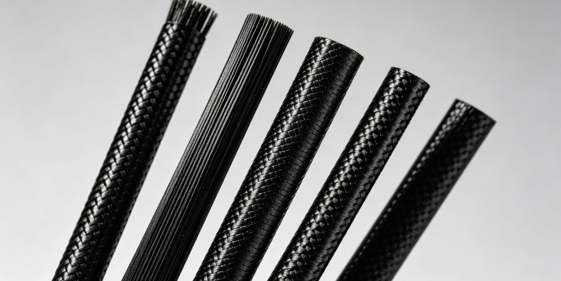
Carbon Fiber Weave Types Explained

Five weave families. Each one behaves very differently under load. Here’s the breakdown.
| Weave Type | Flexibility | Strength Distribution | Best Use Cases |
|---|---|---|---|
| Plain (1×1) | Low | Uniform | Tooling, flat panels |
| Twill (2×2) | Medium | Balanced | Automotive, curved parts |
| Satin (5HS/8HS) | High | Directional | Aerospace fairings |
| Unidirectional (UD) | Very Low | One-directional | Spars, bike frame reinforcement |
| Spread Tow | Medium-High | High | Aesthetic + structural panels |
Each weave type controls how fiber tows interlace with each other. That geometry drives everything that follows. It sets the crimp angle, resin uptake, and drapeability. So it also decides how load travels through your finished laminate.
What Is Carbon Fiber Weave and Why It Determines Your Project’s Success

Carbon fiber weave is the geometric pattern that individual fiber tows interlace to form — and that geometry is not decorative. It is structural. It is mechanical. It separates a part that holds from a part that fails.
Here’s the core physics: every point where two tows cross creates a crimp — a slight curve in the fiber path. Crimp builds stress concentrations. Stress concentrations cost you strength. A plain weave runs a tight over-under-over-under rhythm. That rhythm generates crimp angles of 10–15°, stripping out 15–20% of theoretical fiber strength before any load is applied. A twill weave spans longer between crossovers, cutting that loss to 10–15%. Unidirectional fiber carries zero crimp — and zero weave-induced strength loss.
That math stacks up fast across a laminate.
Weave geometry controls two competing properties that cannot both be maximized at once:
- Stability — how well the fabric holds fiber orientation during handling and cure
- Formability — how well it conforms to curved or complex surfaces
Tight weaves like plain are stable but rigid. Loose weaves like satin drape well over curves but fray fast when cut — 2× faster than tighter constructions. Getting this trade-off wrong goes beyond processing headaches. Misapplying a plain weave to a 3D contour can distort fiber angles by 20–30%, dropping laminate modulus by 15% and triggering delamination.
The weave you pick at the start shapes every result that follows.
Plain Weave Carbon Fiber (1×1): Maximum Stability for Flat Applications

Plain weave is the oldest trick in the textile book — and in carbon fiber, it still earns its place.
The structure is simple. Each fiber tow passes over one, then under one, in a steady alternating rhythm. That tight over-under-over-under pattern creates the familiar checkerboard surface texture. It also locks fibers in place with a density and shear rigidity no other weave can match.
That stability is the whole point. During handling, cutting, and layup, plain weave resists fiber slippage and distortion better than twill or satin constructions. For flat panels, tooling surfaces, and backing plates — where fiber angle accuracy is critical and complex curves aren’t a factor — this is the right choice. You get consistent fiber positioning from start to finish.
Key Mechanical Properties
- Warp tensile strength: ≥ 800 N/25 mm
- Weft tensile strength: ≥ 600 N/25 mm
- Elastic modulus: 230 GPa
- Service temperature range: −50 °C to +300 °C
- Void content (vacuum bagged): < 1%
The trade-off is crimp. All those tight crossover points create concentrated stress nodes. This reduces ultimate strength compared to twill or UD configurations. For flat, load-distributed geometries, that trade-off is fine. For parts with sharp or compound curves, plain weave is not the right fit.
Tow Count and Application Match
| Tow Count | Areal Weight | Best For |
|---|---|---|
| 1K | 80–120 g/m² | UAV skins, phone backs, scale models |
| 3K | 160 g/m² | Auto trim, sporting goods |
| 6K | 320 g/m² | Fan blades, structural panels |
| 12K | 400–600 g/m² | Drive shafts, bridge wraps |
Plain weave carbon fiber fabric works with epoxy, polyester, and vinyl ester resin systems. It wets out fast — under 60 seconds at 25°C. You can run it through hand lay-up, vacuum bagging, RTM, and autoclave processes without issue. Need a weave that stays where you put it? This one does exactly that.
Twill Weave Carbon Fiber (2×2, 3×3, 4×4): The Engineering Sweet Spot Between Strength and Formability

Twill weave solves a problem plain weave can’t. You need real structural strength and the ability to conform to curves — without switching to a different material system. That’s exactly what twill delivers.
The answer is in the crossover count. Plain weave locks every tow in a tight over-one-under-one rhythm. Twill spans multiple tows before crossing — two in a 2×2, four in a 4×4. Fewer crossover points mean fewer crimp nodes. Fewer crimp nodes mean stronger fiber paths. That’s the mechanical logic behind the numbers.
The performance gap is measurable. A 3K 2×2 twill hits 610–640 KSI tensile strength — about 20–28% higher than comparable plain weave constructions at ~500 KSI. Flexural strength goes up too. The fiber path stays straighter under bending loads, and that straightness is what drives the improvement.
2×2 vs 4×4: Choosing Your Trade-off
Twill isn’t one thing. It’s a progression:
| Twill Type | Drape | Stability | Visual Texture |
|---|---|---|---|
| 2×2 | Moderate | Higher | Pronounced herringbone |
| 3×3 | Good | Moderate | Balanced diagonal |
| 4×4 | High | Lower | Fine, subtle ridges |
Each step from 2×2 to 4×4 trades stability for conformability. The 4×4 wraps complex curves with less resistance. The 2×2 holds fiber orientation more consistently during layup. Pick based on what your part geometry demands.
For most structural applications — automotive body panels, bike frames, fairings, and ducts — 2×2 twill is the practical default. It drapes curves that would distort a plain weave. It also keeps the stiffness-to-weight ratio that makes carbon fiber worth using. Plus, the herringbone surface pattern is the look most engineers and designers associate with performance carbon.
Key Specs: 3K 2×2 Twill
| Property | Value |
|---|---|
| Tensile Strength | 610–640 KSI |
| Tensile Modulus | 33.6–34.9 MSI |
| In-plane Tensile | 600 MPa |
| Shear Strength | 75 MPa |
| Areal Weight | 5.7–5.9 oz/yd² |
| Laminate Density | 1.56 g/cm³ |
One limitation worth naming: twill still has crimp. On tight compound curves, even a 4×4 twill will push back. Your geometry needs maximum drape and minimum fiber distortion? Satin weave is the next step up.
But for the broad middle of composite engineering — parts that need both strength and shape — twill weave carbon fiber fabric is where most engineers land. The numbers back it up, and the track record across industries does too.
Satin Weave Carbon Fiber (4HS / 5HS / 8HS): Unmatched Drape for Complex Aerospace Contours

Aerospace fairings don’t forgive bunching. Twill has its limits. Push a compound curve past those limits, and satin weave is what engineers grab.
The logic lives in the name. The “harness number” (HS) tells you how many tows are involved in each interlace. The higher that number, the longer each fiber floats before it crosses another. Longer floats mean fewer crimp points. Fewer crimp points mean the fabric moves, bends, and wraps without resistance.
- 4HS: Weft floats over 3 warps, under 1. You get moderate drape with better stability than higher-harness options. It’s a solid starting point for curved aerospace and structural parts.
- 5HS: Floats over 4 warps, under 1. More conformable than 4HS. Stability drops a notch in exchange.
- 8HS: Floats over 7 warps, under 1. The highest drape, the lowest stability. This is the go-to for complex compound contours like aerospace radomes.
| Property | 4HS | 5HS | 8HS |
|---|---|---|---|
| Surface Smoothness | High | Higher | Highest |
| Fiber Stability | Moderate-High | Moderate | Lowest |
| Layup Difficulty (Complex Curves) | Moderate | Low | Lowest |
That progression carries a real cost: fiber slippage. Fewer interlace points means fewer locks holding tows in place. So 8HS shifts during handling. Weave angles drift. Fiber orientation loses accuracy. For dry fabric, that’s a genuine process risk — one worth taking seriously.
The fix is prepreg. Resin-impregnated satin fabric locks fibers in position before they get a chance to move. Pair it with a system like epoxy System #2000, and you’ve got stable, layup-ready material. Aerospace shops use this approach as standard practice for good reason.
Style 181 (8HS carbon) is a useful reference point: 3.16 oz/yd² (107 g/m²), 0.0035″ (0.089 mm) thick. Light enough to wrap tight contours. Strong enough for structural fairings. Twill bridges and bunches on a radome. 8HS wraps clean. That’s the whole argument.
Unidirectional (UD) Carbon Fiber: Maximum Strength Per Gram in One Direction

Remove every crossover point. Lay every fiber flat and parallel. Strength stops bleeding into geometry.
That’s the core logic of unidirectional carbon fiber. No weave. No crimp. No interlacing tows fighting each other under load. Just fiber running straight in one direction. That’s why UD hits 3× the longitudinal tensile strength of structural steel at one-fifth the weight.
The numbers speak for themselves:
| Product | Tensile Strength | Modulus | Areal Weight |
|---|---|---|---|
| 22.3 oz UD | 696–725 KSI | 32.7–34.1 MSI | 756 gsm |
| 650g UD Tape (HTA40 6K) | 3,950 MPa | 238 GPa | 650 g/m² |
No woven fabric gets close in the 0° direction. Crimp is the reason. Every crossover in a plain or twill weave pushes fiber energy into the matrix instead of along the load path. UD cuts that loss out completely.
The Anisotropy Trade-off You Need to Plan Around
Here’s the catch: UD is strongly directional. Along the fibers, modulus runs 16–18 MSI. Perpendicular to them, it drops to around 1.5 MSI — about ten times weaker. That’s not a flaw. That’s the design contract.
The fix is layup strategy. Stack plies at 0°/90°/±45° and you balance out to a quasi-isotropic ~8–9 MSI. Bias the stack 75%/25% toward the primary load path. You keep most of the directional advantage while covering lateral stress. The laminate does what you tell it to. So you need to tell it with care.
Where UD Carbon Fiber Belongs
UD works best where your load path is known and fixed:
- Wing spars and structural beams — align fibers straight with the primary tension or compression load
- Prosthetic limbs — maximum stiffness per gram where every milligram counts
- Local reinforcement strips — bridges, marine hulls, aerospace stringers where a focused stiffness boost beats re-laminating the whole part
- Ultralight frames — UAVs, model aircraft, rockets, hockey sticks
Processing Notes
One real weak point: the transverse direction tears fast. That weak perpendicular axis makes edge support during cutting non-negotiable. Use a sharp blade. Support the full transverse edge. Plan your cuts before touching the material.
For wet layup, thicker UD fabrics need active resin work. Wet-out doesn’t happen on its own the way it does with woven cloth. Prepreg UD is the cleaner choice for high-performance builds — lower resin ratio, higher fiber volume fraction, stronger finished part.
Panels sit side-by-side in 12″ widths with no gaps. Vacuum bagging or resin infusion handles dry UD well if prepreg isn’t in the budget. Get the fiber direction right. UD delivers more structural output per gram than anything else on this list.
Biaxial Carbon Fiber (±45°): The Shear Strength Specialist for Torsion-Critical Structures
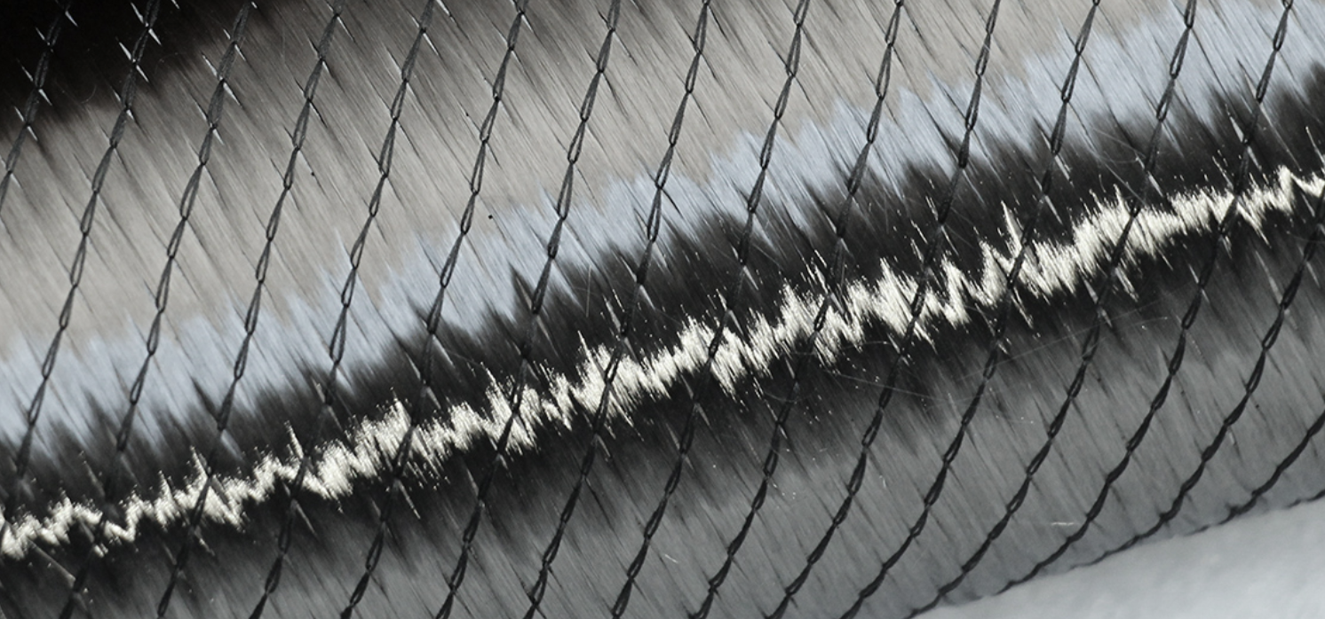
Torsion doesn’t pull. It twists. Twist loads travel at diagonal angles — so fibers oriented at 0° and 90° miss most of the action.
Biaxial carbon fiber fixes that. Two fiber layers stack at +45° and −45°. That puts them right along the shear stress paths that torsion creates. The fibers don’t fight the load geometry — they run with it.
Most biaxial carbon fabric uses a Non-Crimp Fabric (NCF) construction. Two layers stack without interlacing. A light stitch holds them together. No weave. No crimp. That gap matters. A woven ±45° twill brings crimp back at every crossover point. That bleeds shear strength before you apply any load at all. NCF biaxial cuts that loss out completely.
Mechanical Performance at a Glance
| Property | Value | Test Standard |
|---|---|---|
| Tensile Strength | ≥3,400 MPa | ASTM D3039 |
| Tensile Modulus | ≥230 GPa | — |
| Interlaminar Shear Strength | ≥75 MPa | ASTM D2344 |
| Flexural Strength | ≥500 MPa | ASTM D790 |
| Compressive Strength | ≥450 MPa | ASTM D695 |
| Fiber Volume Fraction | ≥60% | ASTM D3171 |
The shear numbers get stronger under real loading conditions. At 20–45° loading angles, interlaminar shear strength jumps 1.3–2.25×. Add moderate through-thickness compression, and shear strength doubles again. In-plane shear modulus and strength climb 25–42% with transverse compression. These aren’t lab results that stay in a report — they show what happens inside a loaded drive shaft or marine hull under combined stress.
Where Biaxial Carbon Belongs
Drive shafts are the clearest fit. Torsional capacity scales with ±45° ply count — add more biaxial plies, get more torque resistance. Biaxial layers beat plain weave and UD configurations in torque transmission. Not by a small margin. The gap is structural.
Marine hulls use biaxial carbon to manage shell twist under combined loading. Drone fuselages place it in torsion zones where UD fiber can’t cover the shear demand on its own.
For filament-wound tubes, helical ±45° windings carry 2× the maximum shear strain compared to all-circumferential layouts. That performance gap grows across fatigue cycles.
Combining Biaxial With UD: The Balanced Laminate
Biaxial carbon rarely works alone in structural builds. Pair ±45° biaxial layers with 0°/90° UD plies, and you get a balanced laminate. It resists both torsion and axial loads. It also stays flat during cure instead of warping.
The split is clean:
– UD layers carry longitudinal stiffness
– Biaxial layers handle shear and torsion
– Together, they cover the full stress envelope
Need pure shear capacity and nothing else? Biaxial is your specialist. Managing mixed stiffness and shear demands? Step up to triaxial or quadraxial multiaxial fabrics.
You can get biaxial carbon in PAN-based T300/T700 fiber, 3K/6K/12K tow counts, and areal weights from 200–600 g/m² — with 200, 240, and 300 g/m² being the most common options. It runs with hand lay-up, RTM, and vacuum infusion. Prepreg formats give you tighter fiber volume control.
Carbon Fiber Weave Type Comparison: Performance, Appearance and Processing at a Glance

Five weave types. Six dimensions that count. Here’s everything side by side.
| Dimension | Plain | Twill | Satin (4–8HS) | UD | Biaxial |
|---|---|---|---|---|---|
| Crimp Level | High | Medium | Low | None | Low–Medium |
| Bidirectional Strength | High | Medium–High | Medium | Low | High |
| Fiber Strength Efficiency | 80–90% | 85–95% | 90–95% | 98–100% | 90–95% |
| Surface Appearance | Checkerboard | Diagonal herringbone | Smooth, lustrous | Flat, non-woven | Even, minimal pattern |
| Drapability | Moderate | Good | Excellent | Poor | Good |
| Processing Difficulty | Low | Medium | High | Low | Medium |
Tow Size Changes the Equation Too
Same weave pattern, different tow count — different part. 3K tow (3,000 filaments) gives you a finer, tighter surface. Cut lines stay sharp. Visual precision improves. The trade-off: 10–20% higher crimp effect, trimming strength by 5–10%. For visible automotive trim or any part where surface quality is a hard requirement, that trade-off makes sense.
12K tow runs coarser and wider. Fewer intersections mean less crimp — a 5–15% strength efficiency gain. Cost drops 15–30% per square meter compared to 3K. The downside is a 20% higher fraying risk during handling. Use 12K where structural output matters more than surface finish: hoods, structural panels, high-volume builds.
What the Numbers Mean for Your Build
Plain weave leads on stability. Its stiffness runs 10–15% higher than twill in flat configurations. Twill and satin close that gap in impact resistance. Twill gives you about 20% better fit over complex curves. UD pulls ahead in pure longitudinal strength — no crimp means no loss. Biaxial handles shear and torsion loads. Neither UD nor standard woven fabrics cover those demands well on their own.
Processing cost follows the same logic. Plain is your baseline. Twill adds 20–30% more layup time on curved geometry. Satin climbs to a 50% cost premium and carries real fray risk from its low fiber stability. UD and biaxial cut out crimping losses — but both need precise ply orientation and careful stitching to perform as designed.
How to Choose the Right Carbon Fiber Weave for Your Application

Selection mistakes follow the same pattern every time. Someone picks a weave that looks right, processes it, then finds the problem after cure.
Here’s how to avoid that.
Match Weave to Geometry First
Part shape is your first filter — not strength numbers, not cost.
Flat panels, tooling, and backing plates: Plain weave. The tight interlacing holds fiber orientation on flat geometry. Fibers stay where you put them. That’s what dimensional control needs.
Curved body panels, fairings, and structural frames: 2×2 twill is the default. It conforms where plain weave would bunch and distort. Push into tighter compound curves? Move to 3×3 or 4×4. Each step up trades a bit of stability for better conformability.
Complex aerospace contours: Satin. Nothing else wraps a radome without distortion.
Match Load Type Second
Geometry handled — now look at how the part actually loads.
- Axial tension or compression along a known load path: UD carbon fiber. Align fibers with the load. Nothing delivers more stiffness per gram in that direction.
- Torsion, shear, or twist: Biaxial ±45°. The fiber angles run along shear stress paths. Woven fabrics at 0°/90° miss most of that load. UD misses all of it.
- Multi-directional or unpredictable loads: Twill or a balanced UD/biaxial laminate stack. Full stress envelope coverage matters more than peak directional efficiency.
Three Mistakes Worth Avoiding
Using plain weave on curved surfaces. You get wrinkled, distorted fiber and a weak laminate. Switch to 2×2 or higher twill.
Relying on UD alone for torsional structures. Single-direction fiber has almost no shear resistance. Add biaxial plies to cover the twist loads.
Over-engineering simple parts. A flat structural panel does not need satin weave. Satin costs more, frays faster, and adds processing steps that flat geometry doesn’t need.
Quick-Reference Selection Table
| Application | Recommended Weave | Why |
|---|---|---|
| Flat panels / tooling | Plain (1×1) | Maximum stability, consistent fiber control |
| Automotive body panels | 2×2 Twill | Strength + drape for curved geometry |
| Complex compound curves | 3×3 / 4×4 Twill | Superior conformability |
| Aerospace contours | Satin (5HS / 8HS) | Unmatched drape, smooth surface |
| Beams, spars, reinforcement strips | UD | Pure longitudinal strength efficiency |
| Drive shafts, torsion tubes | Biaxial ±45° | Direct shear and torsion coverage |
Start with geometry. It narrows the field fast. Load type makes the final call.
Spread Tow Carbon Fiber: The Emerging Weave Technology Worth Knowing

Eighty percent of global carbon fiber production — those 50K, 24K, and 12K industrial tows — goes through a spreading process before it becomes a reinforcement fabric. That number tells you spread tow isn’t experimental anymore. It has become the standard preparation method for high-performance thin-ply applications.
The process is mechanical and precise. Each tow gets pulled across rollers or air jets. This flattens it from a rounded bundle into a wide, thin tape. Filaments fan out side by side in tight alignment. The result: fabric as thin as 0.02 mm with almost no gaps between fibers. No crimp. No stacked thickness from interlacing. Resin spreads across the surface in a uniform layer instead of pooling at crossover points.
That geometry shift produces real efficiency gains:
- PrimeTex 3K spread tow hits 98 g/m² — 12% thinner than conventional 1K fabric at the same areal weight
- 6K spread tow matches the face density of conventional 3K woven cloth
- 12K spread tow achieves what 6K conventional fabric weighs in at
Fewer layers. Same structural output. That math matters on an aerospace panel where every gram costs fuel.
Where the Performance Numbers Land
Straight filaments carry load better than crimped ones. That’s not theory — it’s geometry. Spread tow fabric delivers higher tensile strength and stiffness than traditional twill or plain weave at the same areal weights. Impact resistance goes up too. Less crimp means more fibers absorb energy across a wider area. Stress doesn’t concentrate at interlace nodes.
The applications that drove adoption are not hard to spot. Wing skins, fuselage panels, satellite structures, racing monocoques, wind turbine blades — these are all places where excess weight has a measurable cost. There is zero tolerance for wasted material.
The Honest Trade-offs
Spread tow costs more upfront. The equipment required for the spreading process carries a high entry threshold. Specifications stay limited — not every tow count comes in every areal weight. This technology fits low-volume, high-performance work: aerospace prototypes, racing components, precision sporting goods. Large-scale mass production is not where it operates yet.
The numbers still work in its favor. You need fewer plies. Resin uptake is cleaner. The flatter surface finish cuts post-processing time. Long-term, those savings offset the entry cost. Short-term, the price is real — worth factoring in before you specify it.
Conclusion
Picking the right carbon fiber weave is not a small call. It’s what separates a part that holds up from one that breaks under pressure.
Plain weave holds its shape. Twill drapes and impresses. Satin fits complex curves. UD gives you raw directional strength. Biaxial carbon fiber takes on the twist and shear forces that other weaves miss. Each pattern has a job to do. The real mistake isn’t choosing the “wrong” one. It’s choosing without knowing what each one is built for.
Now you know the difference. The next move is yours.
Browse the HyperX Carbon fabric lineup to match your project to the right carbon fiber weave pattern. Not sure which one fits your layup design? Reach out and we’ll work through it with you. The best composite parts start with a clear conversation.
Contact HyperX Carbon – Your Trusted Chinese Carbon Fiber Customization Partner
Ready to develop high-performance carbon fiber materials or custom forged carbon fiber parts tailored specifically for your project?
HyperX Carbon is your long-term strategic partner with over 20 years of expertise in advanced composites. We specialize in delivering aerospace-grade forged carbon fiber custom solutions, along with fully personalized prepreg, tubes, sheets, and lightweight carbon fiber structural components for automotive, drone, eVTOL, and medical applications.
We don’t just supply materials — we provide end-to-end customization support:
- Stable premium supply chain using Toray, Mitsubishi, and Hengshen raw materials
- AS9100D certified production tailored for aerospace and UAV requirements
- Rapid prototyping carbon fiber component in just 5-8 weeks, with monthly capacity over 180,000 parts
- Competitive pricing with 15-18% cost savings on forged carbon solutions
- Full customization flexibility: from T700 and T1100G to ultra-high modulus grades, with tailored layups, finishes, and performance specifications
Whether you’re an eVTOL developer, automotive OEM, drone manufacturer, or medical device engineer, HyperX Carbon delivers bespoke material selection, structural optimization, and manufacturing solutions that match your exact technical and performance needs — with consistent batch-to-batch quality and reliable delivery.
Get in touch today for a free technical consultation, personalized quote, or custom material samples.
📧 Email: [email protected] 🌐 Website: https://www.hyperxcarbon.com/ 📞 Phone/WhatsApp: +86 15623270276 (English support available)
Let’s co-create your next lightweight innovation together. Contact HyperX Carbon now and stay ahead in the low-altitude economy and advanced composites market.
HyperX Carbon – Not just a supplier, but your dedicated carbon fiber customization expert.