Every engineer who’s ever specified a carbon fiber tube knows the frustration. Conflicting data sheets, vague supplier specs, a dozen variables — any one of them can make or break a structural design.
You might be optimizing a drone frame for the best stiffness-to-weight ratio. Or sourcing carbon fiber tubing for a robotic arm. Or trying to figure out why two tubes with the same outer diameter perform so differently under load. The answers are scattered — never in one place.
This guide fixes that.
You’ll find everything here: layup construction, wall thickness tolerances, tensile strength comparisons, and selection logic for specific industries. All the details you need to specify, source, and use carbon fiber tubes with confidence — covered in one place.
What Is Carbon Fiber Tubing? Material Composition & Core Advantages Over Metal
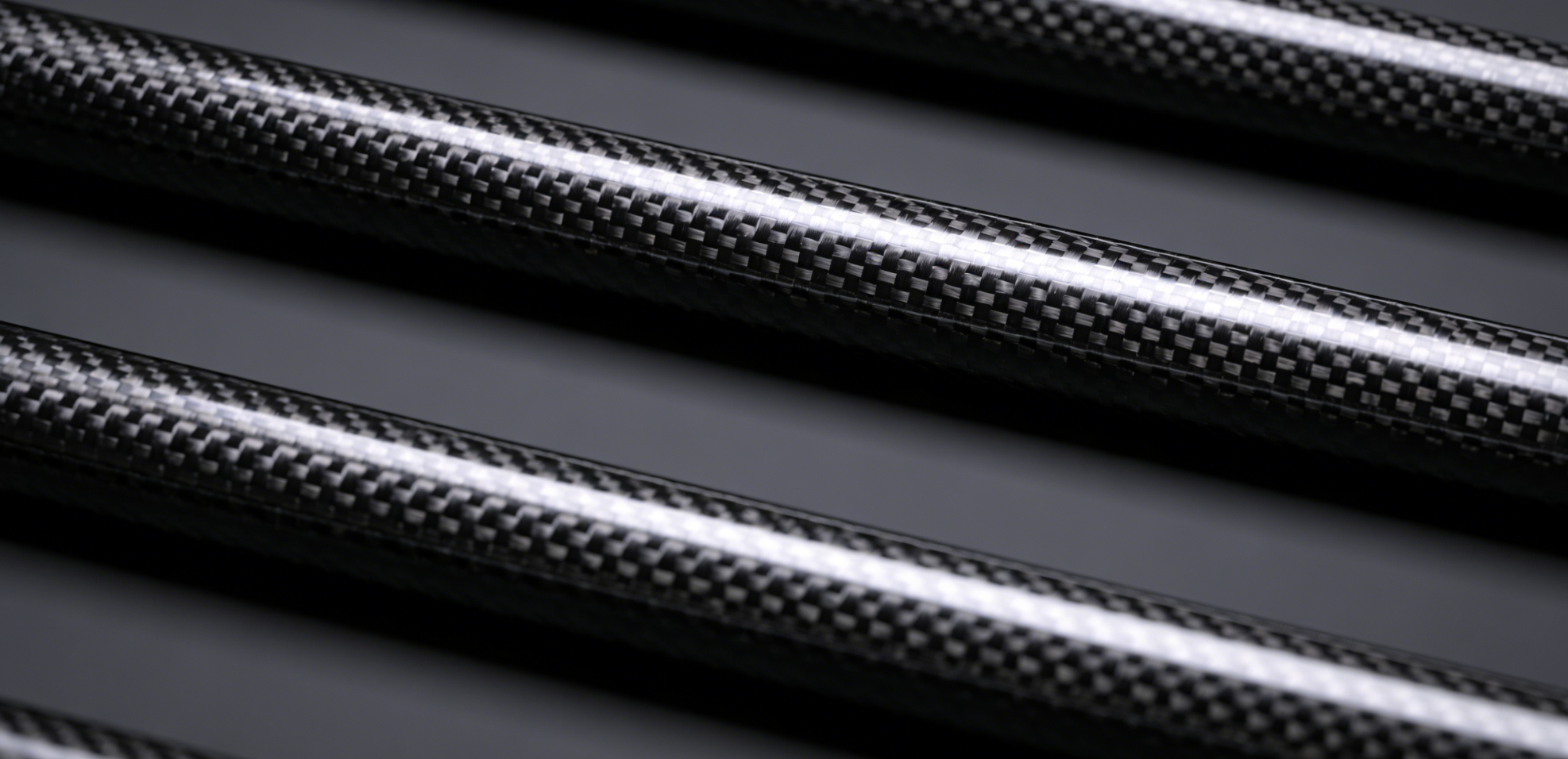
A carbon fiber tube is a composite structure built with real precision. The carbon fibers run 5–10 micrometers in diameter, held together in an epoxy resin matrix at a 33:67 resin-to-fiber ratio. That sounds technical. Here’s what it means for you: the tube weighs a fraction of steel, holds its shape under brutal loads, and never rusts.
The fibers start as polyacrylonitrile (PAN) — a polymer precursor that makes up about 90% of commercial carbon fiber production. Manufacturers run it through stabilization, carbonization, and graphitization at temperatures up to 3,000°C. By the end, almost nothing remains except carbon atoms. They align and lock into a crystalline structure built for tensile performance.
Fiber Grade Determines Performance
Not all carbon fiber tubing performs the same. The modulus grade of the fiber changes everything:
-
Standard Modulus (SM) — 1.5× stiffer than aluminum. This is the go-to grade for drones, sporting equipment, and structural frames.
-
Intermediate Modulus (IM) — 2× stiffer than aluminum. You’ll find it in robotics and aerospace secondary structures.
-
High Modulus (HM) — 3× stiffer than aluminum. It gets close to steel-level stiffness at a fraction of the weight.
The Numbers Against Metal
Here’s where carbon fiber tubing earns its price premium:
|
Material |
Tensile Strength |
Density |
Stiffness-to-Weight |
|---|---|---|---|
|
Carbon Fiber Tube |
600–700 ksi |
0.05 lb/in³ |
160 × 10⁶ |
|
6061-T6 Aluminum |
65 ksi |
0.10 lb/in³ |
100 × 10⁶ |
|
4130 Steel |
125 ksi |
0.30 lb/in³ |
100 × 10⁶ |
Carbon fiber tubing cuts 40% of the weight compared to equivalent-strength aluminum, and 70% compared to steel. Stainless steel runs 5.5× heavier for comparable cross-sections.
Raw strength is only part of the story. Carbon fiber tubes bring two advantages metal can’t touch: a near-zero coefficient of thermal expansion (CTE) that keeps dimensions stable across temperature swings, and zero corrosion — no rust, no pitting, no surface degradation over time. In fatigue cycling environments, carbon fiber outlasts both aluminum and steel across repeated load applications.
The wall construction reflects this level of control. Each prepreg layer adds 0.006 inches of thickness. Finished walls typically run from 0.010″ up to 1/4″. Fiber direction is a deliberate engineering choice — unidirectional along the length, hoop-wound around the circumference. Metal tube specs don’t work that way. They treat the material the same in every direction, which carbon fiber design never does.
Types of Carbon Fiber Tubes: Round, Square, Rectangular & Custom Profiles Explained

Shape is a structural decision — not an aesthetic one.
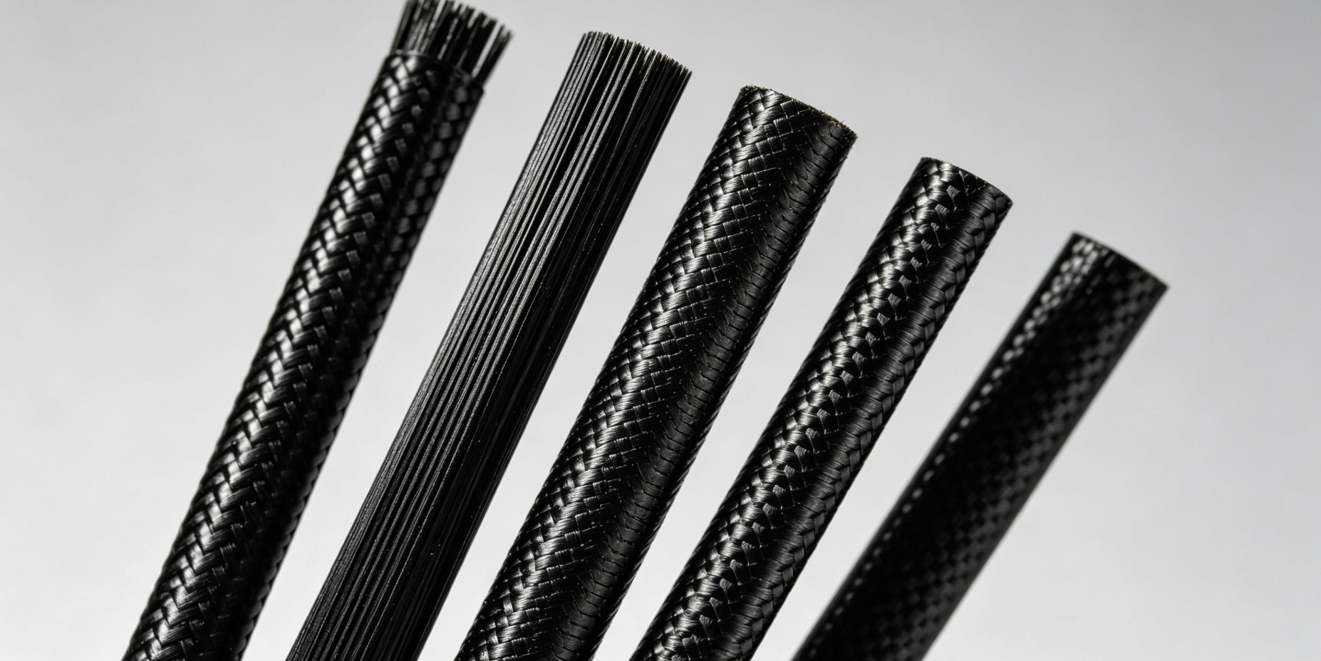
Carbon fiber tubing comes in far more forms than most engineers expect. Round tubes dominate because they spread stress evenly in every radial direction. That makes them the go-to choice for shafts, booms, and frames. But the profile range goes much deeper: square, rectangular, oval, elliptical, hexagonal, octagonal — plus fully custom cross-sections for cases where standard geometry won’t cut it.
The Profile Lineup
-
Carbon fiber round tube — the workhorse. Great for torsion-heavy applications: drone arms, robotic links, telescoping poles.
-
Carbon fiber square tube — stronger moment resistance in bending. The SQ40TW (40×40mm, 1mm wall) delivers 4.74 KNm² stiffness at just 0.24 kg/m.
-
Carbon fiber rectangular tube — directional stiffness by design. Built for structures that load mainly on one axis.
-
Custom profiles — oval, octagon, tapered, or fully custom cross-sections. We can produce up to 500mm diameter and 5m lengths.
Wall Thickness Is a Design Variable
Each prepreg layer adds about 0.006 inches. Stack more layers, and the wall gets thicker. It’s that straightforward. Wall thicknesses range from 0.010″ for thin-wall drone booms up to 1/4″ for heavy structural use.
A quick reference for round tube stiffness versus size:
|
OD / ID (mm) |
Wall (mm) |
Stiffness (KNm²) |
Weight (kg/m) |
|---|---|---|---|
|
10 / 8 |
1.0 |
0.03 |
0.04 |
|
26 / 23 |
1.5 |
0.91 |
0.17 |
|
50 / 47 |
1.5 |
7.06 |
0.34 |
Stiffness jumps fast as diameter grows. Going from a 10mm to a 50mm tube multiplies stiffness by over 200×. You add just 0.30 kg/m in weight to get there.
Standard lengths top out at 96 inches for most sizes. Need something longer? Use internal or external connectors to join sections together cleanly.
Carbon Fiber Tube Sizes & Specifications: OD, ID, Wall Thickness & Tolerance Standards
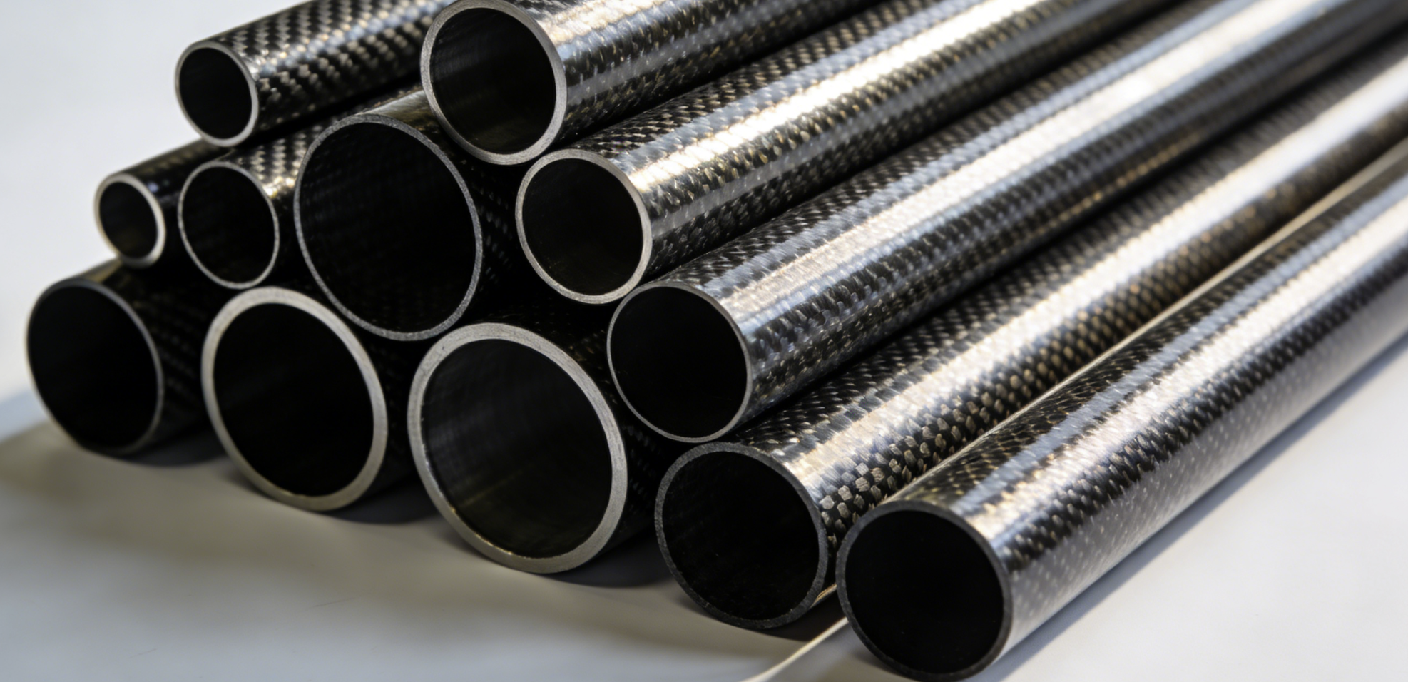
Get the sizing wrong on a carbon fiber tube and you’re not just losing money. You’re losing credibility, time, and possibly structural integrity. Here’s the full breakdown.
The Size Spectrum: From Micro to Industrial Scale
Carbon fiber tubing covers an enormous range. At the small end, 4–6mm OD tubes have walls as thin as 0.3mm. They weigh just 8–18 g/m — light enough for medical guide tubes and FPV drone arms where every gram counts. Step up to 25–30mm OD, and walls grow to 1.5–3.0mm. Weight climbs to 120–220 g/m.
Most engineering projects fall in the medium range (10–50mm OD):
|
OD / ID (mm) |
Wall (mm) |
Weight (kg/m) |
|---|---|---|
|
10 / 8 |
1.0 |
0.04 |
|
22 / 19 |
1.5 |
0.14 |
|
30 / 27 |
1.5 |
0.20 |
|
42 / 39 |
1.5 |
0.29 |
|
50 / 47 |
1.5 |
0.34 |
You’ll notice 1.5mm wall thickness repeats across several diameters. That’s no accident. It’s a manufacturing sweet spot — it holds structural performance without adding unnecessary weight.
Large-scale industrial tubes reach 602mm ID and up to 5 meters in length. Production tops out at 500mm OD. That range covers aerospace components, wind energy structures, and heavy industrial rollers.
Wall Thickness by Application
Wall thickness is a deliberate choice. Match it to what the tube needs to do:
-
0.3–0.8mm — FPV drone arms, medical guide tubes. Less material, serious weight savings.
-
0.8–1.5mm — Camera gimbals, robotic linkages. Good stiffness-to-weight balance for precision motion systems.
-
1.0–2.0mm — Sprayer booms, automotive cables. Extra wall handles vibration and side loads.
-
1.5–3.0mm — Industrial rollers, surveying spars. Built for structural duty where bending under load is a real concern.
Tolerance Standards You Can Spec From
Tighter tubes need tighter tolerances. The numbers here are stricter than most engineers expect:
|
Diameter Range |
OD Tolerance |
|---|---|
|
2–5mm |
±0.15mm |
|
6–30mm |
±0.05mm |
|
30–100mm |
±0.08mm |
|
100–300mm |
±0.2mm |
Length tolerances follow the same pattern: ±0.5mm under 2000mm, ±2mm beyond that. For press-fit joints or precision assemblies, these figures decide whether your design fits right on the first build — or after several frustrating attempts.
Material density sits at 1.5–1.6 g/cm³. Pair that number with your OD, ID, and wall dimensions, and you can calculate exact tube weight before ordering a single part.
Mechanical Properties Deep Dive: Tensile Strength, Modulus, Shear Strength & Fatigue Life
Numbers don’t lie — but vague numbers do. A supplier spec sheet that says “high strength” is hiding a lot of nothing behind three words.
Here’s what matters when you load a carbon fiber tube under structural stress.
Tensile Strength & Elastic Modulus
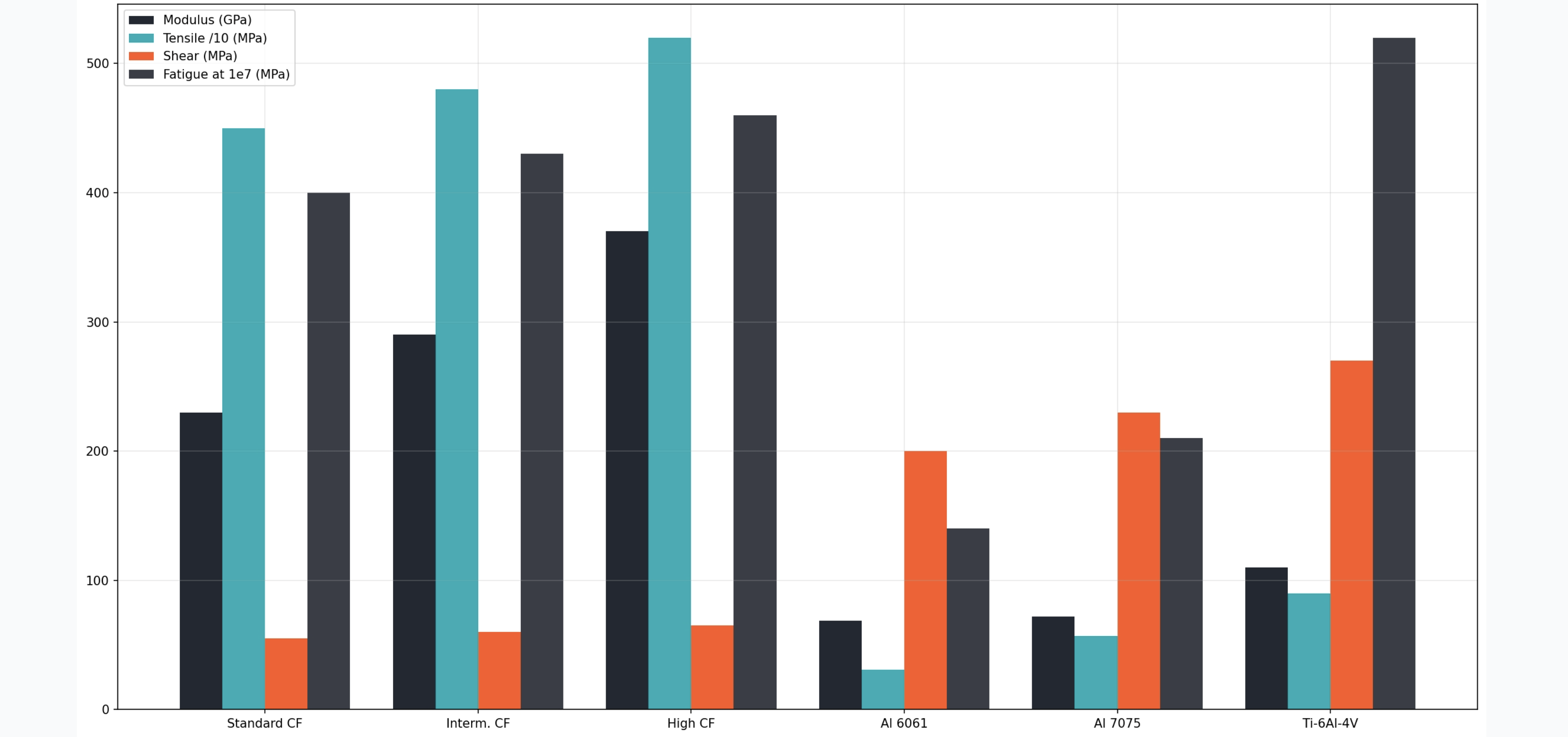
Carbon fiber tubes built from standard-modulus fiber deliver tensile strength in the 600–700 ksi range — that’s 4,100–4,800 MPa. This isn’t a marketing figure. It’s what the fiber architecture produces when the layup is done right.
Modulus controls stiffness, not just strength. Here’s how the three grades stack up:
-
Standard-modulus: ~230 GPa
-
Intermediate-modulus: ~290 GPa
-
High-modulus: 370+ GPa
Higher modulus means less deflection under the same load. That matters for robotic arms, optical booms, and precision frames. In those applications, dimensional drift is a failure mode — not just a minor annoyance.
Shear Strength
Torsional loading is where shear strength takes center stage. For well-built carbon fiber tubing, interlaminar shear strength (ILSS) runs 40–70 MPa. The exact number depends on layup angle and resin system.
Tubes with ±45° fiber plies handle torsion far better than unidirectional constructions. So for drone arms, drive shafts, and robotic joints — any application with twisting loads — specify the layup angle. Don’t leave it open to interpretation.
Fatigue Life: Where Carbon Fiber Has a Clear Edge
This is where carbon fiber tubing pulls away from metals. The tensile numbers alone don’t show the full picture.
Aluminum:
– 6061-T6 reaches a fatigue strength of 140 MPa at 10⁷ cycles — with no endurance limit. It keeps degrading past that point.
– 7075-T6 does better at ~210 MPa, but the same degradation issue applies.
Steel and Titanium:
– Plain carbon steel holds around 340 MPa at 10⁷ cycles.
– High-strength steel pushes past 700 MPa.
– Ti-6Al-4V lands between 450–590 MPa — strong performance at just 56% of steel’s density.
Carbon fiber tubes don’t follow classical S-N curve behavior. Under high-cycle fatigue, well-laminated carbon fiber structures show minimal stiffness degradation well past 10⁷ cycles. This holds true under controlled stress ratios.
Stress ratio (R = σ_min/σ_max) plays a real role here:
– Tensile mean stress reduces fatigue amplitude.
– Compressive mean stress extends fatigue life.
Build that into your design from the start.
The bottom line: for cyclic-load applications — landing gear, suspension linkages, repetitive-motion robotics — carbon fiber tubing outlasts aluminum. You also get a lower weight penalty. Both advantages in one material.
Carbon Fiber Tube Applications by Industry: Aerospace, Drones, Robotics, Sports & Medical
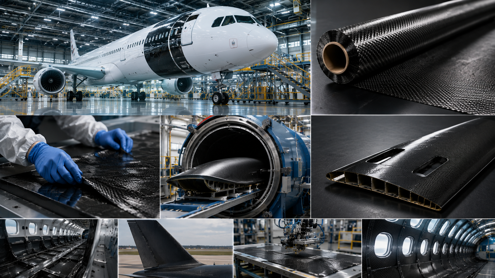
The Boeing 787 is 52% carbon fiber by weight. The Airbus A350XWB hits close to the same number. That’s not a materials trend — that’s a structural philosophy, built in composite.
Carbon fiber tubes show up across modern engineering. But each industry uses them for different reasons. Here’s what that looks like in practice.
Aerospace & Defense
Aerospace leads the market. The sector held the largest share of carbon fiber tube value in 2023. The aviation carbon fiber market alone is projected to grow from USD 2.58 billion (2025) to USD 6.55 billion by 2035 at a 9.76% CAGR.
The parts list is substantial:
– Wing spars
– Fuselage panels
– Bulkheads
– Empennages
PAN-based carbon fiber dominates this segment. It offers high strength, high stiffness, and a continuous fiber structure. Pitch-based fiber covers brake systems and high-temperature parts. In those cases, thermal conductivity matters more than raw tensile strength.
Weight reduction is the main driver. Less mass means better fuel efficiency, lower emissions, and more payload capacity. Cut one kilogram from an airframe, and that saving pays off across thousands of flight cycles.
Drones & UAVs
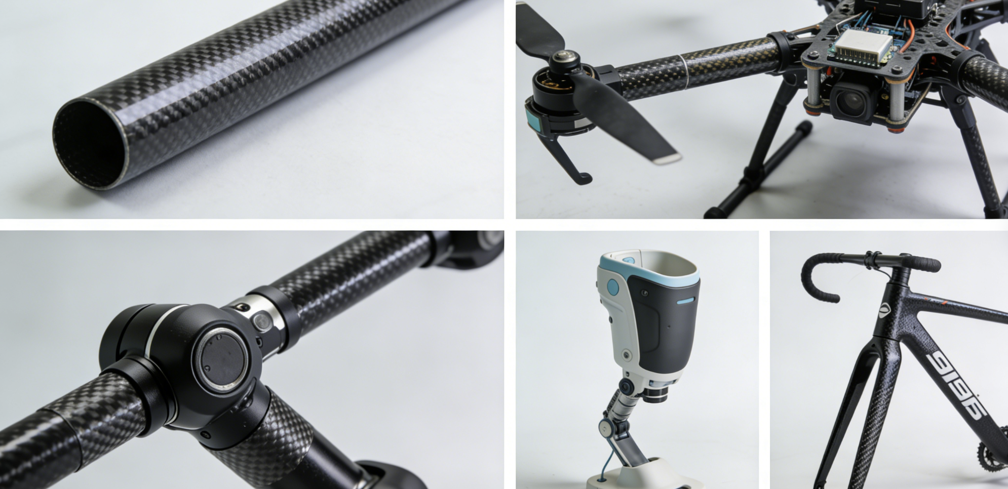
Military and commercial UAVs need the same strength-to-weight ratio as full-scale aircraft — just at a much smaller scale. Carbon fiber round tubes form the core structure of most UAV frames. You’ll find them in arm booms, fuselage spars, and landing struts.
The military fixed-wing segment is on track for the fastest growth in the aviation carbon fiber category. U.S. defense procurement is a big factor, along with expanding military UAV programs globally.
Robotics
No large published dataset tracks carbon fiber tube use in robotics directly. Still, the engineering case is clear. Robotic arms face cyclic loading, tight dimensional tolerances, and strict weight limits all at once. Carbon fiber tubing — intermediate-modulus grades with ±45° layups in particular — handles all three at the same time. That’s hard to match with other materials.
Sports & Cycling
High-performance bicycle frames are the most visible consumer application. Carbon fiber tubes give competitive cyclists and manufacturers the stiffness and weight savings they need. The same thinking applies to motorsport components. There, every gram of unsprung mass has a real effect on lap times.
Medical
Medical device use is a smaller, more focused segment. But the material properties are a strong fit. Carbon fiber tubing offers:
– Radiolucency — it doesn’t block imaging scans
– Corrosion resistance — stable in clinical environments
– Dimensional stability — holds its shape under load
These qualities make it a practical choice for imaging-compatible structural parts and surgical guide systems.
How to Select the Right Carbon Fiber Tube: A Step-by-Step Engineering Selection Guide

Most selection mistakes happen before anyone opens a datasheet. The real error is upstream — in the question being asked. Engineers chase wall thickness or modulus before they’ve defined the load. Fix the sequence first. Everything else falls into place.
Here’s the workflow: Load Path → Dimension → Wall Thickness → Surface & Finish → Tolerance Class. First pass takes 30 seconds. A fully specified tube takes five minutes.
Step 1: Define Your Load Type First
Every other decision depends on this one.
-
Axial loads (tension or compression) → maximize 0° fiber content
-
Bending loads (cantilevers, booms) → a larger OD gives you much greater stiffness gains
-
Torsional loads (shafts, drive joints) → ±45° layup is non-negotiable
-
Combined loads → use a hybrid layup; angle the fibers toward the dominant stress
Step 2: Lock In Your Diameter
A larger OD increases stiffness faster than any other variable. Stiffness scales with the fourth power of radius — that’s a big jump per millimeter. Compact assemblies and weight-critical builds limit how far you can go, though. Match your OD and ID to mating hardware before moving on. Changing it later costs more than the tube itself.
Step 3: Calculate Wall Thickness — Three Inputs
A. Define your loads: bending moment M (N·m), torsion T (N·m), axial force F (N).
B. Use allowable stress: σ_allow = 600 MPa for T300 fiber, 800 MPa for T800.
C. Use safety factors: dynamic loading ×1.5, impact ×2.0, UAV frames ×1.3.
Thicker walls address strength. A well-planned layup addresses stiffness. These are two separate problems — don’t treat them as one.
Step 4: Choose Modulus Grade
|
Grade |
Modulus |
Best For |
|---|---|---|
|
Standard |
103 GPa |
General structural, drones |
|
Intermediate |
150 GPa |
Robotics, precision frames |
|
High |
300 GPa |
Optical systems, aerospace |
|
Ultra-High |
500+ GPa |
Stiffness-critical, minimal deflection |
Step 5: Specify Tolerances Early
Two classes cover most engineering work:
-
P1 (±0.05mm OD, ≤0.10mm/m straightness) — UAVs, robotics, press-fit assemblies. Inspect with Go/No-Go gauges and ultrasonic.
-
P2 (±0.10mm, ≤0.30mm/m) — industrial structures. Calipers and visual inspection work fine here.
Set your tolerance class before you build a prototype. Tightening tolerances on a finished design means rework. That rework never fits anyone’s budget.
Step 6: Address Environment and Integration
Resin choice drives long-term durability. Temperature range, UV exposure, chemical contact, and moisture cycling all push you toward different resin systems. Pick the right one for your actual conditions. For machining — CNC drilling, slotted ends, bonded joints, telescopic fits — plan for machinability from day one. The right tooling cuts carbon fiber cleanly. The wrong approach causes delamination. There’s no middle ground.
Carbon Fiber Tube vs Aluminum Tube vs Steel Tube: A Full Comparison for Engineers

Three materials. One structural slot. Your choice affects everything — weight budget, fatigue life, cost, and how the part behaves when it fails.
Here’s the full picture.
|
Property |
Carbon Fiber |
Aluminum (6061) |
Steel (4130) |
|---|---|---|---|
|
Tensile Strength (MPa) |
2,070–6,000 |
230–572 |
670 |
|
Density (g/cm³) |
1.6 |
2.7 |
~7.8 |
|
Specific Strength (KSI) |
1,800 |
350 |
417 |
|
Specific Stiffness (MSI) |
200 |
100 |
100 |
|
Fatigue Tolerance |
Near unlimited |
Moderate |
Defined limit |
|
Impact Tolerance |
Low (brittle) |
High (ductile) |
High (ductile) |
|
Corrosion Resistance |
Immune |
Moderate |
Variable |
Where Carbon Fiber Wins
Specific strength tells the real story. Carbon fiber tubes reach 1,800 KSI — about 5× aluminum and 4× chromoly steel. Specific stiffness doubles both metals at 200 MSI. In weight-critical structures, that gap is real. No other material closes it.
The weight difference is just as clear: 40–45% lighter than aluminum, 5× lighter than steel at the same cross-section. In aerospace and UAV design, that’s not a nice bonus — it’s a core mission requirement.
Fatigue performance is another strong point. Carbon fiber tubes don’t build up damage over time within their design range. Aluminum has no endurance limit — it keeps degrading past 10⁷ cycles. Steel has set crack thresholds that require regular inspection. Carbon fiber avoids both issues.
Corrosion? Not a concern. Carbon fiber stays stable against acids, bases, and solvents. Steel needs coatings. Even stainless grades like 304 and 316 need specific chromium and nickel levels to hold up.
Where Metal Still Wins
This is where honest engineering matters more than marketing.
Carbon fiber is brittle. Past its load limit, it cracks and splits — no yield, no visible warning. Aluminum and steel absorb impact energy through plastic deformation. That predictable failure behavior is critical in safety-sensitive designs.
Take motorsport roll structures as an example. A steel roll hoop adds 2.6 kg over carbon — that works out to about 0.08 seconds per lap at Monaco. Engineers take that weight penalty on purpose. Steel bends in a crash. Carbon breaks apart. The extra weight buys a controlled, predictable collapse. That’s not a trade-off — it’s the right call.
Cost is the other hard limit. Carbon fiber tubes run about 8× the price of equivalent steel sections. In high-volume industrial builds where weight isn’t the main concern, that cost gap is hard to justify at procurement.
The Practical Decision Framework
-
Weight is the top priority → Carbon fiber. Nothing else comes close.
-
Impact loads or crash energy absorption → Steel or aluminum.
-
High-cycle fatigue applications → Carbon fiber.
-
Budget-limited structural builds → Aluminum first, steel second.
-
Corrosive environments → Carbon fiber or stainless steel, based on impact risk.
The real mistake isn’t choosing the wrong material. It’s choosing the right material for the wrong load case.
Frequently Asked Questions About Carbon Fiber Tubes
These questions come up all the time — in spec reviews, supplier emails, and late-night forum threads. Here are straight answers.
What tensile strength should I expect from a carbon fiber tube?
Standard-modulus tubes deliver 640–739 ksi across most commercial grades. Composites at 60% fiber volume come in around 512 ksi using Toray 250°F epoxy resin systems. High-strength grades exceed 650 MPa. High-modulus grades hold above 550 MPa. The number you care about depends on your fiber volume fraction and resin system — not just the fiber grade alone.
What’s the usable temperature range?
For pultruded tubes, the maximum service temperature is 80°C. Roll-wrapped epoxy systems run from –30°C to +100°C for continuous use. The glass transition temperature (Tg) sits around 140°C. Go past Tg and the resin softens. The fiber stays intact. The structure doesn’t.
How much does water absorption matter?
Less than most engineers expect. Carbon fiber tubes absorb less than 1.5% by weight. Dimensional changes from moisture stay negligible in most applications.
What’s the compressive strength?
Around 215 ksi (1.47 GPa) for well-laminated standard-modulus tubes. Flexural strength runs around 260 ksi. The flexural modulus lands at 18.0 Msi. These figures drop fast if the layup has voids or the fiber volume falls below 60%.
How thick is each prepreg layer?
Each layer is 0.006 inches thick. A 0.060-inch wall equals 9–10 layers in a roll-wrapped construction. That math comes in handy for calculating minimum wall thickness for a given load case.
Conclusion
Carbon fiber tubes aren’t just a material upgrade — they’re an engineering decision that pays off over time. Lighter structures move faster, fatigue less, and outlast metal counterparts across demanding applications — from drone frames to surgical robotics.
At this point, you have the full picture. You know how carbon fiber tubing is built. You can read a spec sheet with confidence. And you can match wall thickness, layup angle, and modulus to your actual load requirements — not just a catalog guess.
The next move is yours.
Still comparing options? Start with your application’s dominant stress type — bending, compression, or torsion. Let that narrow the field. Ready to source? hyperxcarbon.com offers custom carbon fiber round tubes, square tubes, and rectangular profiles — with engineering support included.
The best carbon fiber tube isn’t the strongest one. It’s the right one for your project.
Contact HyperX Carbon – Your Trusted Chinese Carbon Fiber Partner
Ready to source high-performance carbon fiber materials or custom forged carbon fiber parts from China?
HyperX Carbon is a leading manufacturer with 20+ years of expertise, specializing in aerospace-grade forged carbon fiber, prepreg, tubes, sheets, and lightweight automotive/drone/medical components. We offer:
-
Stable supply chain with premium raw materials (Toray, Mitsubishi, Hengshen)
-
AS9100D certified production for aerospace & UAV applications
-
Rapid prototyping (5-8 weeks) and monthly capacity exceeding 180,000 parts
-
Competitive pricing with 15-18% cost savings on forged carbon solutions
-
Full customization: from T700/T1100G to ultra-high modulus grades
Whether you’re an eVTOL developer, automotive OEM, drone manufacturer, or medical device engineer, HyperX delivers consistent quality, batch-to-batch reliability, and reliable delivery.
Get in touch today for a free consultation, custom quote, or material sample.
📧 Email: [email protected]
🌐 Website: https://www.hyperxcarbon.com/
📞 Phone/WhatsApp: +86 15623270276 (English support available)
Let’s build your next lightweight innovation together – contact HyperX Carbon now and stay ahead in the low-altitude and advanced composites market.