Every structural decision has consequences. A failed drone arm at 400 feet or a collapsed robotic exoskeleton mid-operation leaves no room for “I assumed it was strong enough.” That’s not an engineering position — it’s a liability.
Carbon fiber tube strength isn’t a single number you pull from a datasheet. It depends on several factors:
-
Fiber orientation — how the layers are aligned affects load distribution
-
Wall geometry — wall thickness and diameter determine stiffness and buckling resistance
-
Manufacturing process — filament winding, pultrusion, and layup each produce different results
-
Load case — axial compression and bending loads behave very differently
This guide gives you clear, usable data. You’ll find the mechanical property benchmarks that matter, the calculations engineers use to size tubes for axial compression and bending loads, and honest material comparisons between carbon fiber and aluminum tube strength — no marketing spin, just real numbers.
Specifying tubing for a UAV frame, a medical device, or an industrial automation component? The data you need to make a solid, defensible decision is right here.
Carbon Fiber Tube Strength, Load Capacity & Engineering Guide 2026
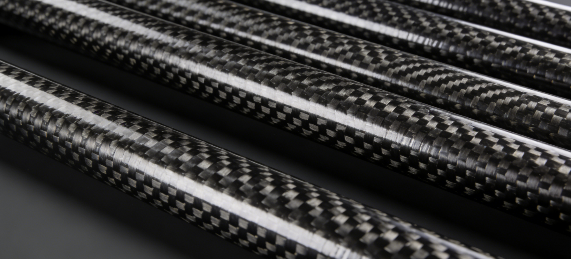
Carbon fiber tube strength numbers are precise and testable. Read them right, and they tell you exactly what a tube can handle.
Here are the 2026 benchmarks for standard CFRP tube (60% fiber volume, Toray 250°F epoxy, ASTM-verified):
|
Property |
Value |
Standard |
|---|---|---|
|
Tensile Strength |
1,860 MPa (270 ksi) |
ASTM D-3039 |
|
Compressive Strength |
1,482 MPa (215 ksi) |
ASTM D-695 |
|
Flexural Strength |
1,793 MPa (260 ksi) |
ASTM D-790 |
|
Flexural Modulus |
124 GPa (18.0 Msi) |
ASTM D-790 |
|
Tensile Modulus |
135 GPa (20.0 Msi) |
— |
|
Interlaminar Shear |
96 MPa (14 ksi) |
ASTM D-2344 |
One number stands out above the rest. The 90° tensile strength drops to just 76 MPa — that’s a 97% drop from the axial figure. Load orientation is not a minor detail. It defines how the tube performs in real use.
What Makes Carbon Fiber Tubes So Strong: Core Mechanical Properties

Four mechanical properties define how a carbon fiber tube performs under real structural load. Understanding each one on its own is the difference between a precise material choice and a costly mistake.
Tensile strength is where CFRP stands out the most. Unidirectional fibers aligned along the tube’s axis carry pulling forces with remarkable efficiency — up to 512 ksi in high-performance grades. Think of it as a material built for pure tug-of-war conditions.
Compressive strength runs at 65–80% of tensile. That gap has a clear mechanical cause: microbuckling and fiber kinking. Fibers that handle tension with ease fail differently under compression. They fold before they fracture.
Flexural strength (1,500–2,500 MPa) controls bending behavior. Roll-wrapped tubes outperform pultruded ones here. The reason: hoop fibers resist crushing forces during three-point bending events. Pultruded tubes lack that fiber orientation, so they give way sooner.
Interlaminar shear strength (ILSS) often gets ignored, but it matters. It sits at 50–150 MPa and marks the critical failure point under torsion or off-axis loading. Push a tube past this limit and the layers separate — not the fibers themselves.
One number ties all of this together: CFRP density is just 1.55 g/cm³. That low mass produces a specific tensile strength 4–5× greater than steel and 2× greater than aluminum. So you get a material that is light and stiff at the same time. That is why engineers keep coming back to carbon fiber for demanding structural applications.
Carbon Fiber Tube Strength-to-Weight Ratio vs. Aluminum, Steel & GFRP
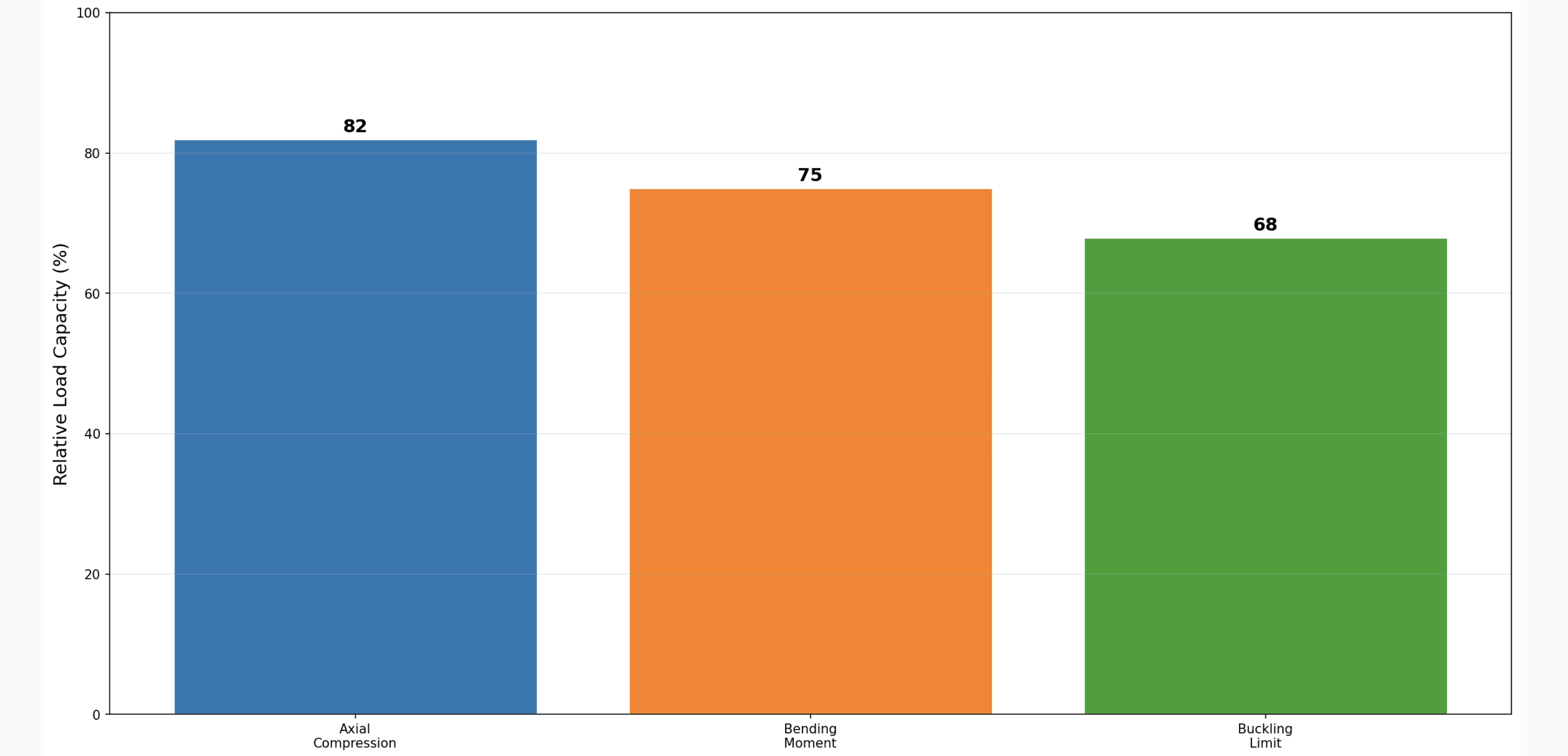
Numbers don’t lie, but they need context. Here’s what matters most for structural material selection.
CFRP’s specific strength — tensile strength divided by density — ranges from 1,335 to 3,026 MPa·cm³/g under standard grades. In 2026 high-tenacity benchmarks, it hits 3,200. Aluminum lands at 110–185. Steel tops out around 130. That gap isn’t small. CFRP sits in a completely different category.
|
Material |
Tensile Strength |
Density (g/cm³) |
Specific Strength (MPa·cm³/g) |
|---|---|---|---|
|
CFRP |
2,070–5,400 MPa |
1.55 |
1,335–3,200 |
|
Aluminum |
~310 MPa |
2.7 |
110–185 |
|
Steel (4130 chromoly) |
400–2,600 MPa |
7.8 |
50–130 |
|
GFRP |
Inferior to CFRP |
~1.8 |
400–600 |
What Those Ratios Mean in Practice
CFRP vs. chromoly steel: the strength-to-weight advantage is 15–22:1. Against aluminum, it’s 5–10:1. Against GFRP, 3–5:1.
Here’s what those numbers look like in real engineering:
-
vs. Steel: Same load capacity, 75–80% less mass. CFRP delivers 3× the tensile strength of chromoly (2,070 MPa vs. 670 MPa) at one-fifth the weight.
-
vs. Aluminum: You get a 50% lighter tube. Wall thickness drops by 40–60%. Stiffness stays 2–5× higher. That’s not a tradeoff — that’s a structural upgrade.
-
vs. GFRP: GFRP costs about 40% of CFRP. Your application needs less than 500 MPa·cm³/g specific strength? Budget is tight? GFRP makes sense. Push past that threshold and GFRP costs you more in structural performance than it saves on price.
The 2026 Hybrid Consideration
One data point worth tracking: CFRP-GFRP and CFRP-metal hybrid composites now deliver ~20% higher load capacity than pure CFRP in certain setups. Specific strengths reach 1,600–3,500 MPa·cm³/g. Cost runs 0.6–0.8× pure CFRP. Stiffness gains hit 10–15%. Your performance needs exceed GFRP’s ceiling but pure CFRP feels too expensive? Hybrids are the practical choice in 2026.
How Manufacturing Process Determines Carbon Fiber Tube Load Capacity
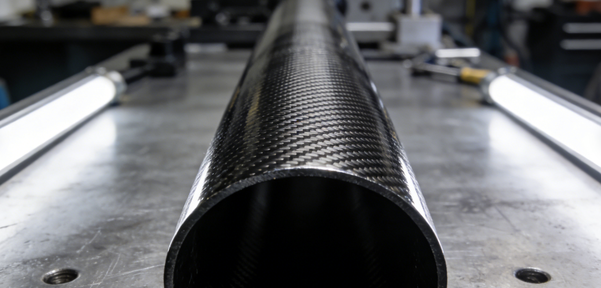
Three factories. Three identical tube dimensions. Three different load capacities. That’s not a quality control failure — that’s manufacturing physics at work.
The process that produces your carbon fiber tube is not a footnote in the spec sheet. It is the spec sheet.
Filament Winding: Built for Extreme Axial and Torsional Loads
Filament winding lays continuous fiber at precise angles around a rotating mandrel. You get axial tensile strength up to 5,000 MPa — the highest available through any standard tube manufacturing method.
The real engineering advantage here is programmability. Change the winding angle, and you change the entire load profile:
-
0° dominant layup → maximize axial tensile and compression
-
±45° dominant layup → optimize torsion and shear resistance (used in 75% of torsional driveshaft designs)
-
90° layers → reinforce hoop strength and radial stability (10–20% of the stack)
A real-world example: UAV spar tubes using a [(0°)₆/(±45°)₂/(90°)₁]ₛ layup achieved an 18 kN ultimate load at just 420 g. Wind turbine driveshafts built with filament winding hit 30% weight reduction versus steel — with no loss in structural integrity.
Pultrusion: Consistency Over Complexity
Pultrusion pulls fiber through a resin bath and a heated die. You get dimensional consistency and high-volume repeatability — not peak performance.
Compression strength lands around 1,200 MPa. Tensile strength reaches 3,500 MPa with a modulus of 230 GPa. Those are solid numbers. The constraint is fiber orientation: pultrusion is mostly unidirectional. Off-axis loads expose that weakness fast.
Long, slender pultruded tubes are buckling-limited. Watch your L/D ratio. For standard structural profiles with axial and predictable loads, pultrusion is efficient and cost-effective. Push it into complex load environments and it underperforms.
Prepreg Autoclave / Roll-Wrapping: Precision Engineering at Scale
Prepreg processing — autoclave-cured or roll-wrapped — gives you the highest bending performance and tightest dimensional control of any method.
Flexural modulus reaches 200–600 GPa. Bending strength exceeds 2,000 MPa. A [(0°)₄/(90°)₁/(±45°)₁]ₛ layup at 65% fiber volume produces tensile strength between 4,500–5,800 MPa. Wall tolerance holds at ±0.05–0.15 mm. Outer diameter tolerance: ±0.008 inches.
That level of precision matters in medical devices, aerospace assemblies, and robotics. These are applications where fit tolerances and load predictability are non-negotiable.
Process Selection at a Glance
|
Process |
Peak Strength |
Best Load Type |
Dimensional Tolerance |
Volume Fit |
|---|---|---|---|---|
|
Filament Winding |
Axial Tensile: 5,000 MPa |
Torsion, pressure, axial |
±0.1 mm |
Medium–high batch |
|
Pultrusion |
Tensile: 3,500 MPa |
Uniform axial |
High consistency |
High volume |
|
Prepreg / Roll-Wrap |
Bending: 2,000+ MPa |
Bending, multi-axis |
±0.05–0.15 mm |
Custom, precision |
The rule is simple: match the process to the load direction. Axial-dominant applications need filament winding or pultrusion. Bending-critical components need prepreg layup. Torsion-heavy designs — driveshafts, robot joints — demand ±45° winding. Pick the wrong process and no wall thickness adjustment will fix the structural gap.
Carbon Fiber Tube Load Capacity: Axial Compression, Bending Moment & Buckling Limits
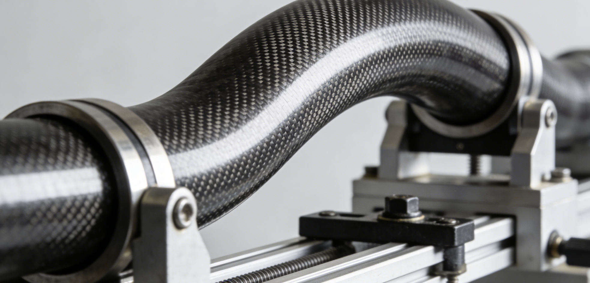
Load capacity isn’t a fixed value stamped on a tube. It shifts with geometry, length, end constraints, and how the load arrives.
Three failure modes control carbon fiber tubes in structural use: axial compression buckling, bending moment failure, and interlaminar shear under combined loading. Buckling is the one that catches engineers off guard most often. The tube doesn’t crush. It folds.
Axial Compression: Buckling Governs, Not Crushing
A 25mm OD × 2mm wall tube at 300mm length carries about 80 kg (0.8 kN) before buckling failure. Scale up to a short, thick roll-wrapped tube and that limit climbs past 2 tonnes. The difference isn’t material grade — it’s the L/D ratio.
Here’s the key relationship: load capacity scales with (wall thickness / OD)³. Double the wall thickness relative to diameter and you don’t double capacity — you increase it by eight times. End constraints matter just as much. A pinned-pinned column buckles at half the load of a fixed-fixed column with the same dimensions.
Keep your working load at 30–50% of the buckling limit. For dynamic applications — UAV arms, robotic actuators, anything with impact or vibration — use a safety factor of 3–5×.
Bending Moment: Geometry and Fiber Angle Together
Bending stiffness climbs with larger OD and thicker walls. Deflection scales with span² — double the span and your deflection goes up four times. That surprises most engineers until it causes a structural failure.
A useful reference point: 1-meter legs flex 3–4 inches under 170 kg total load. For bending-critical designs, ±45° and 90° fiber layers must be part of the layup — not optional reinforcement.
|
Tube Type |
Compressive Capacity |
Context |
|---|---|---|
|
High-strength CF (short) |
>2 tonnes |
Test condition |
|
Roll-wrapped CF |
>1 tonne |
Structural mid-range |
|
Steel equivalent |
\~1 tonne |
Higher mass |
|
Aluminum equivalent |
\~0.5 tonne |
Lowest capacity |
The data is clear: CFRP matches or beats steel in compression capacity at a fraction of the weight. But the geometry has to be right. A slender tube with the wrong L/D ratio fails at 20% of its material’s theoretical limit.
Carbon Fiber Tube Deflection & Bending Stress Calculation Guide
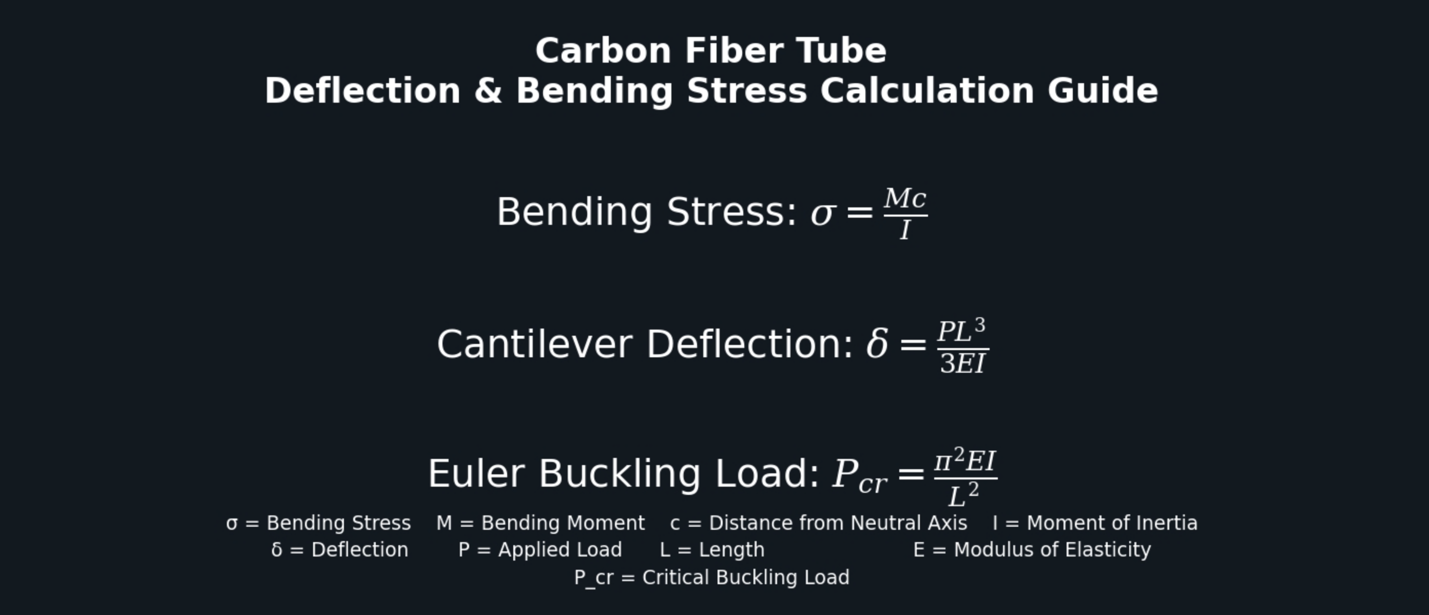
Three formulas separate a tube that holds from one that doesn’t. Learn them once, and you’ll stop guessing at structural decisions.
The Core Equations
Bending stress: σ = Mc / I
Cantilever deflection: δ = PL³ / 3EI
Euler buckling critical load: P_cr = π²EI / L²
The moment of inertia connects all three: I = π(OD⁴ − ID⁴) / 64, where ID = OD − 2 × wall thickness.
Worked Example: Drone Arm Under Load
A 20mm OD × 1.5mm wall roll-wrapped carbon fiber tube, 300mm long, carrying a 5 kg (49 N) tip load. E = 120 GPa.
-
ID = 20 − 3 = 17mm → 0.017m
-
I = π(0.020⁴ − 0.017⁴) / 64 = 4.80 × 10⁻⁹ m⁴
-
Deflection δ = (49 × 0.3³) / (3 × 120×10⁹ × 4.80×10⁻⁹) = 0.766 mm ✓
-
Bending stress σ = (49 × 0.3 × 0.010) / 4.80×10⁻⁹ = 30.6 MPa — well below CF tensile limits exceeding 1,000 MPa ✓
-
Buckling load P_cr = (9.87 × 120×10⁹ × 4.80×10⁻⁹) / 0.09 = 52.1 N — just 3.1 N above the 49 N applied load. That margin is tight. For dynamic or impact conditions, go with a thicker wall or a shorter span.
Verification Limits
-
Deflection: keep below L/150 (2mm max for a 300mm span)
-
Stress safety factor: 3–5× yield for dynamic applications
-
Euler validity: L/OD > 10 — below that ratio, use short-column analysis
Run complex multi-axis load cases through ANSYS FEA (input E = 70–240 GPa, Poisson = 0.3). For quick pre-sizing, try meracalculator.com or omnicalculator.com. Both tools handle round-tube cantilever calculations well and give you fast, solid results.
Wall Thickness & Outer Diameter Selection: Engineering Decision Framework
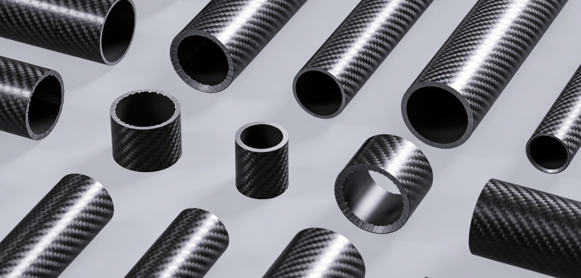
Wall thickness and outer diameter aren’t style choices. They’re the two variables that decide whether your carbon fiber tube holds or fails.
Start with a simple rule: minimum wall thickness is 1.5 mm for spans under 50 mm. Past that, wall thickness scales with span squared. Double the span and your required wall doesn’t double — it quadruples.
|
Span |
Minimum Wall Thickness |
|---|---|
|
50 mm |
1.5 mm |
|
100 mm |
6.0 mm |
|
150 mm |
13.5 mm |
The D/t Ratio: Your Primary Design Check
The outer diameter to wall thickness ratio (D/t) does more to control buckling than any other single factor.
|
Application |
D/t Range |
Typical Spec |
|---|---|---|
|
Light-duty / thin-wall |
20–50 |
OD 20 mm, t = 1 mm |
|
Standard structural |
10–20 |
OD 50 mm, t = 3–5 mm |
|
Heavy-duty / pressure |
5–10 |
OD 273 mm, t = 9.27 mm |
Keep D/t below 20 for structural rigidity. Drop it below 10 for pressure-bearing applications. Push past 30 and you’re not building a column — you’re building a failure point.
Application-Specific Starting Points
-
Drones and robotics: OD 20–30 mm, wall 1–2 mm. A 25 mm OD × 1.5 mm wall handles torsional loads below 10 Nm without issue.
-
Industrial robot arms: OD 50 mm, wall 3 mm (D/t ≈ 17). Bending moment capacity: 50–100 Nm.
-
Medical devices: OD 10–25 mm, wall 1–1.2 mm. Torque limit stays at or below 50 Nm.
The Hidden Cost of Overdesign
Every extra millimeter of wall adds mass. In weight-sensitive applications, that mass adds up fast.
On a 50 mm OD tube, going from t = 3 mm to t = 5 mm adds 62 g per meter. That’s a 67% weight penalty for a 1.5× safety margin you may not need. On a 273 mm OD tube, moving from Schedule 10 (t = 4.19 mm) to Schedule 40 (t = 9.27 mm) pushes weight up by 35%.
The balance rule: maximum wall = required wall × 1.2 to 1.5. For drones and medical devices, hold your safety margin at 1.5× the calculated minimum. Go beyond that and you’re not gaining safety — you’re gaining dead weight.
Selection procedure in five steps:
1. Calculate minimum wall: t = 1.5 mm × (L/50)²
2. Select OD based on application range (20–900 mm)
3. Confirm D/t ≤ 20 for rigidity, ≤ 10 for pressure
4. Verify tolerances: OD ±0.40 mm, wall minimum −12.5% of nominal
5. Pick your schedule: target Sch 10–20 for light-duty, Sch 40 for standard structural loads
Fiber Orientation & Layup Design for Specific Load Cases
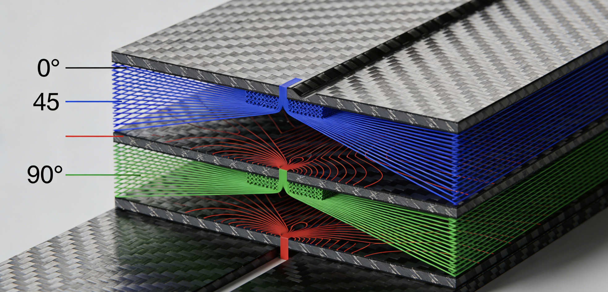
Fiber orientation is where carbon fiber engineering either gets precise or gets expensive.
The fiber angle decides which loads the tube resists — and which ones it ignores. Get this wrong and no amount of wall thickness will save you.
Four orientations. Four distinct jobs:
-
0° plies carry axial tension and compression. Align fibers along the tube axis and you maximize stiffness in that direction. Monocoques, spars, and bike frames all depend on this.
-
±45° plies handle shear and torsion. The +45°/−45° pair forms an “X” pattern that resists twisting forces. Skip these in a driveshaft or robot joint and you’ve built a torsional failure into the design.
-
90° plies resist transverse loads, radial pressure, and crushing. They stop a tube from buckling under lateral force. Pressure vessels need them. Cross members need them.
-
Quasi-isotropic (QI) layups — such as [0/45/−45/90]s — spread stress evenly across all directions. Aerospace skins and EV structural panels use QI because loads hit from multiple directions at once.
The All-0° Mistake
A full [0°] laminate looks strong on paper. Under pure axial tension, it is. Under any torque or shear load, it fails fast. You get shear-driven buckling, interlaminar separation, and zero warning. The fix is straightforward — add ±45° plies any time torsion or off-axis loading is present.
Layup Selection by Load Case
|
Stacking Sequence |
Best For |
Stress Behavior |
|---|---|---|
|
[0°]₈ |
Axial tension/compression |
Maximum X-direction stress |
|
[90°]₈ |
Transverse, radial pressure |
Minimum X-stress, maximum Y-strain |
|
[0/45/−45/90]s |
Multi-axis, combined loads |
Uniform XY shear; outer layers carry peak compressive stress |
|
[0/45/−45/60]s |
Balanced tensile/compressive |
Near-uniform stress distribution throughout |
Four-Step Layup Procedure
-
Identify the primary load — axial demands 0°, torsion demands ±45°, transverse demands 90°
-
Balance the stack — always pair ±45° plies adjacent and symmetric about the midplane
-
Target QI for complex environments — 25% allocation to each of 0°/±45°/90°
-
Put high-load angles on the outside — outer plies carry the most bending stress. Place 0° there for tension-dominant designs.
One constraint that trips up even experienced designers: corner radii must be at least 3× the ply thickness. Go tighter and fiber integrity breaks down at the bend. Keep fiber volume between 50–70% for prepreg layups. Drop below that range and resin-rich zones create weak spots. Those spots show up as early failure under fatigue loading.
Real-World Application Load Cases: Drones, Robotics, Industrial & Medical
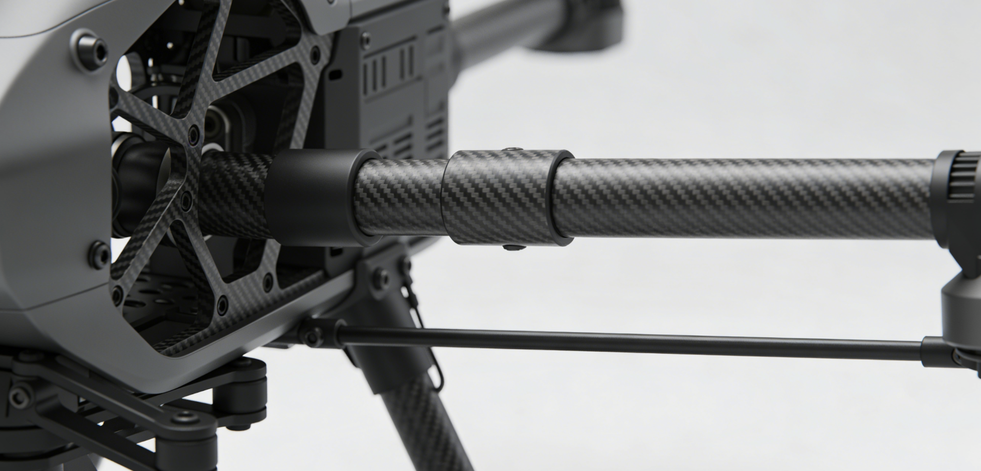
Four industries. Four different structural demands. One material that keeps showing up in all of them.
Drones
Drone arms carrying 5–20 kg payloads generate bending moments up to 100 Nm. The tube spec that survives that load must be light and stiff at the same time. Dead weight kills flight time before the mission even starts.
Medical drone payloads show just how precise sizing needs to be. Sub-2 kg delivery (vaccines, medications) commands 45% of the 2023 market. Heavier organ transport is a different story. Take this example: 3.8 kg of blood moved over 25.2 km in 13 minutes, Israel 2023. That kind of mission calls for a different airframe design. The top selection drivers: minimum mass, maximum vibration damping.
Robotics & Industrial Arms
Industrial robotic arms run under 200 kN axial compression. Fatigue requirements exceed 10⁶ cycles. Compressive stiffness isn’t optional — it’s the core specification. Warehouse automation sits at $4.93B (2023) and keeps growing. Every gram you cut at the arm tip turns into speed gains and energy savings across millions of cycles.
Medical Devices
Precision runs this space. Torque limits hold at 50 Nm. Dimensional tolerances leave no room for error. Biocompatibility adds a strict layer of material qualification. Aluminum and steel can’t clear that bar as cleanly — carbon fiber can.
Medical drone infrastructure is scaling fast — from $430M in 2025 to $1.18B by 2030 (22.19% CAGR). Rotary-wing platforms hold 78.77% of that market in 2026. AED delivery via drone runs 67% faster than ambulances. Carbon fiber tubes aren’t a side detail in that outcome. They’re what makes it possible.
How to Test & Verify Carbon Fiber Tube Strength: Standards & Methods

Datasheets are promises. Testing is proof.
Three ASTM standards handle the actual verification work:
-
ASTM D3039 — tensile strength, elastic modulus, failure strain. Run at least five specimens. Record the mean, standard deviation, and coefficient of variation.
-
ASTM D6641 — compressive strength and critical buckling load. Keep fixture alignment within 0.5°. Miss that threshold and your buckling data becomes worthless.
-
ASTM D7264 — flexural strength and modulus. Choose 4-point bending over 3-point. The constant moment zone produces cleaner, more reliable results.
Lab numbers and field performance don’t match — and that gap is no surprise. Grip failures alone can cut measured tensile strength by 20–50%. Temperatures above 60°C or humidity above 60% can drop resin modulus by another 15–30%. These aren’t rare edge cases. They’re everyday service conditions.
Use a 1.5–2.0× safety factor on lab data before making any engineering decisions. Test 10+ full-scale prototypes under real service loads. Also run an ultrasonic C-scan (ASTM E213) as a cross-check. It catches internal delaminations and voids larger than 0.5mm — defects that visual inspection simply won’t find.
Looking at supplier test reports? Confirm fiber volume falls between 50–60%. Check that CoV stays below 10%. Make sure the test specimens match your actual layup — not a generic [0/90]s coupon that has nothing to do with your tube geometry.
Carbon Fiber Tube Engineering FAQ: 8 Questions Engineers Ask Most
Eight questions. Every engineer gets to them at some point.
Q1: What’s the maximum axial compressive load my tube can handle?
Short, thick-walled tubes (L/D < 10) approach 360 MPa before buckling takes over. Use the Euler formula: P_cr = π²EI / L². E = 230 GPa for UD tubes.
Q2: How do I calculate cantilever deflection?
δ = PL³ / 3EI. A larger OD and thicker walls bring δ down. Add ±45°/90° layers to boost bending stiffness.
Q3: What happens when I double the wall thickness?
Bending and torsional stiffness jump 8×. Compressive buckling resistance goes up 4×. Tensile capacity grows 2× — a straight, proportional gain.
Q4: Which process handles high compression best?
Go with filament-wound or roll-wrapped tubes using optimized ±45°/0° layups. Keep your L/D ratios short. Keep walls thick.
Q5: Can hybrid composites boost load capacity?
Yes. Carbon-aramid hybrid layups deliver a verified 20% increase. Your tensile baseline climbs from 3.5 GPa to 4.2 GPa. These are a strong fit for high-impact applications.
Q6: When does high-modulus carbon fiber make sense?
Buckling is your critical failure mode? That’s where high-modulus grades shine. Grades at 3,500+ MPa raise P_cr by 20% at the same weight. The trade-off is real though — brittleness goes up, and so does cost.
Q7: What tolerances should I specify?
– ID: ±0.1 mm
– Wall thickness: ±0.1 mm
– Fiber volume: 45% minimum
– Porosity: below 2%
Q8: Which ASTM standards govern tube testing?
Three cover everything you need:
– ASTM D3039 for tensile
– D3410 for compression
– D790 for flexure
Together, they cover every primary failure mode.
Conclusion
Engineering with carbon fiber tubes isn’t guesswork. It comes down to geometry, material science, and manufacturing precision — all working together.
Calculating carbon fiber tube bending stiffness for a UAV boom? Comparing carbon fiber vs aluminum tube strength for a robotic arm? Or just trying to nail the wall thickness before your first prototype? The principles in this guide give you a solid framework. One that holds up under real load conditions.
The bottom line: no other structural material gives you this mix of tensile performance, weight efficiency, and design flexibility at scale. That said, the material performs only as well as the decisions you make selecting it.
Your next step is straightforward:
-
Take the load case you’re working with
-
Run it through the deflection and buckling formulas in this guide
-
Match your geometry to a tube spec with an honest safety margin
Ready to skip the back-and-forth? Browse HyperX Carbon’s engineering-grade tube catalog or reach out to our team. We’ve seen the load cases. We’ll help you get the spec right.
Contact HyperX Carbon – Your Trusted Chinese Carbon Fiber Partner
Ready to source high-performance carbon fiber materials or custom forged carbon fiber parts from China?
HyperX Carbon is a leading manufacturer with 20+ years of expertise, specializing in aerospace-grade forged carbon fiber, prepreg, tubes, sheets, and lightweight automotive/drone/medical components. We offer:
-
Stable supply chain with premium raw materials (Toray, Mitsubishi, Hengshen)
-
AS9100D certified production for aerospace & UAV applications
-
Rapid prototyping (5-8 weeks) and monthly capacity exceeding 180,000 parts
-
Competitive pricing with 15-18% cost savings on forged carbon solutions
-
Full customization: from T700/T1100G to ultra-high modulus grades
Whether you’re an eVTOL developer, automotive OEM, drone manufacturer, or medical device engineer, HyperX delivers consistent quality, batch-to-batch reliability, and reliable delivery.
Get in touch today for a free consultation, custom quote, or material sample.
📧 Email: [email protected]
🌐 Website: https://www.hyperxcarbon.com/
📞 Phone/WhatsApp: +86 15623270276 (English support available)
Let’s build your next lightweight innovation together – contact HyperX Carbon now and stay ahead in the low-altitude and advanced composites market.