Finding the right carbon fiber tube shouldn’t feel like solving a puzzle with missing pieces.
Say you need a 2mm micro-tube for a precision sensor housing. Or a 1 inch carbon fiber tube for a drone frame. Or a 248mm large-diameter section for an aerospace structural application. In each case, the gap between the right size and the almost right size is real — a failed prototype, a costly redesign, or a structural compromise that doesn’t show up until it’s too late.
This guide gives you a complete, engineering-grade size reference in one place. You’ll find:
-
Metric dimensions from 10mm to 248mm
-
Standard inch sizes
-
Wall thickness selection logic
-
Real custom options
Engineers, fabricators, and procurement specialists — this covers what you need to make the right call, fast.
Carbon Fiber Tube Size Chart: Full Range From 10mm to 248mm (Metric & Inch)
Numbers don’t lie — and in carbon fiber tube selection, the right number is everything.
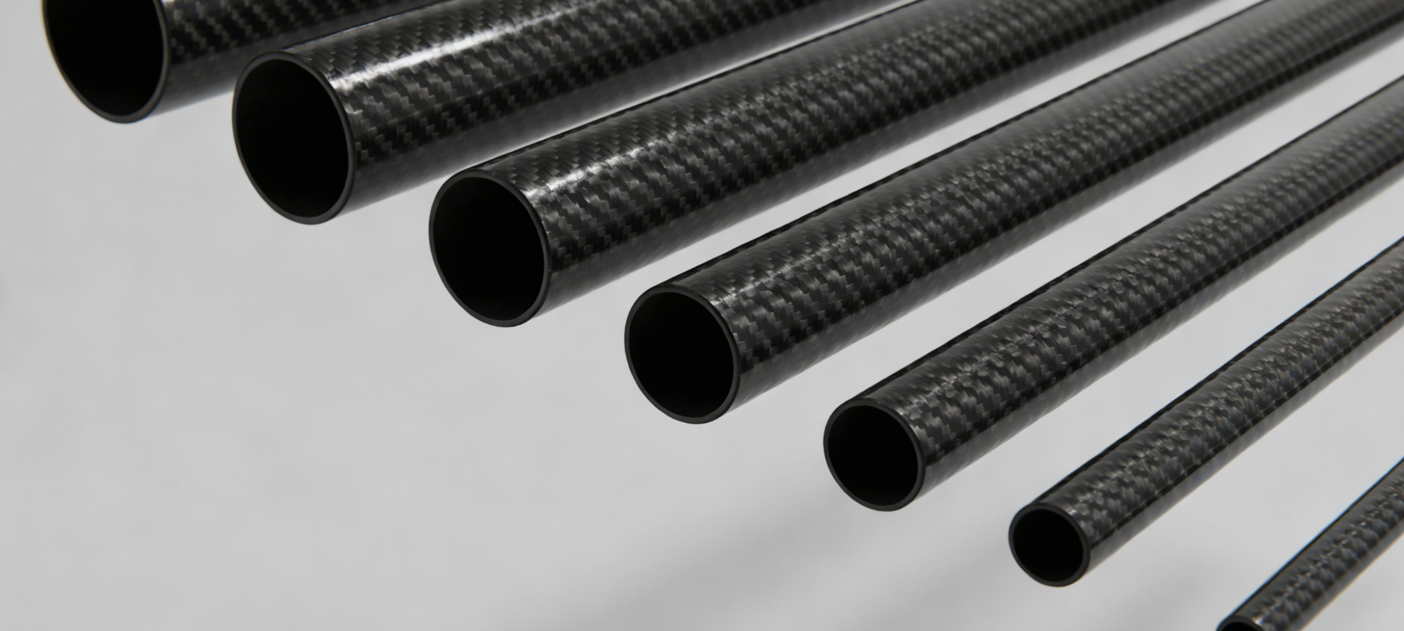
The full stock range runs from 10mm OD at the micro end to 248mm at the structural extreme. Each size has three dimensions that matter: outer diameter, inner diameter, and wall thickness. Get all three right, and your build fits first time.
Metric Size Reference
|
OD |
ID |
Wall |
Length |
Weight |
|---|---|---|---|---|
|
10mm |
8mm |
1mm |
1000mm |
~43 g/m |
|
12mm |
10mm |
1mm |
1000–2000mm |
~53 g/m |
|
13–15mm |
varies |
1mm |
248mm (RC spec) |
— |
Weight increases at a consistent rate. For 1mm wall prepreg construction, expect 10–15 g/m for every additional 5mm OD.
Inch-to-Metric Conversion
|
Inch |
Exact mm |
Nearest Stock |
|---|---|---|
|
1″ |
25.4mm |
25mm OD |
|
1.5″ |
38.1mm |
38mm or 40mm OD |
|
2″ |
50.8mm |
50mm OD |
Tolerance Classes
Two grades cover most applications:
-
P1 Aviation (±0.05mm) — OD ground to ±0.0127mm; cuts fit errors by 50% in tight builds
-
P2 Industrial (±0.10mm) — Standard roll-wrapped tolerance; works well for most structural builds
Wall thickness runs from 0.25mm (ultra-thin) to 6.35mm (quarter-inch structural). Each layer adds around 0.15mm. You can fine-tune thickness anywhere between 0.08mm and 0.25mm per ply.
Small Diameter Carbon Fiber Tubes (10mm–20mm OD): Specs for Drones, Robotics & Precision Instruments

A 10mm carbon fiber tube weighs just 15 grams per meter. That’s lighter than a AAA battery. Yet it handles tensile loads over 2,000 MPa. This strength-to-weight ratio is why this size range leads in drone frames, robotic linkages, and precision instrument housings.
Wall thickness drives everything here. A 12mm OD tube with a 0.5mm wall gives you EI bending stiffness of 2.0–4.0 Nm². That’s the sweet spot for racing drone arms where every gram counts. Go up to 16mm OD with a 2.0mm wall, and stiffness jumps to 8–12 Nm². You get a tube that holds up under sustained load on vibration-heavy UAV arms.
Key specs by application:
-
FPV drone arms (8–20mm): OD tolerance ±0.05–0.10mm. Surface Ra <1.6μm stops motor misalignment past 0.5° under 5G load.
-
Medical/robotics (10–16mm): ID tolerance tightens to ±0.03mm. Surface Ra runs 0.4–0.8μm, meeting ISO 9001 standards.
-
Camera gimbals (15–20mm): ±0.05mm tolerance gives you 20–30% smoother footage compared to aluminum equivalents.
Carbon fiber also has a negative CTE of -0.5 to -1.0 ppm/°C. This keeps tube geometry within 0.1mm across a range of -20°C to 80°C. For precision instruments, thermal drift is a real failure risk. This material fights it passively, with no extra engineering needed.
1 Inch Carbon Fiber Tube (25.4mm OD): Most Popular Standard Size Explained
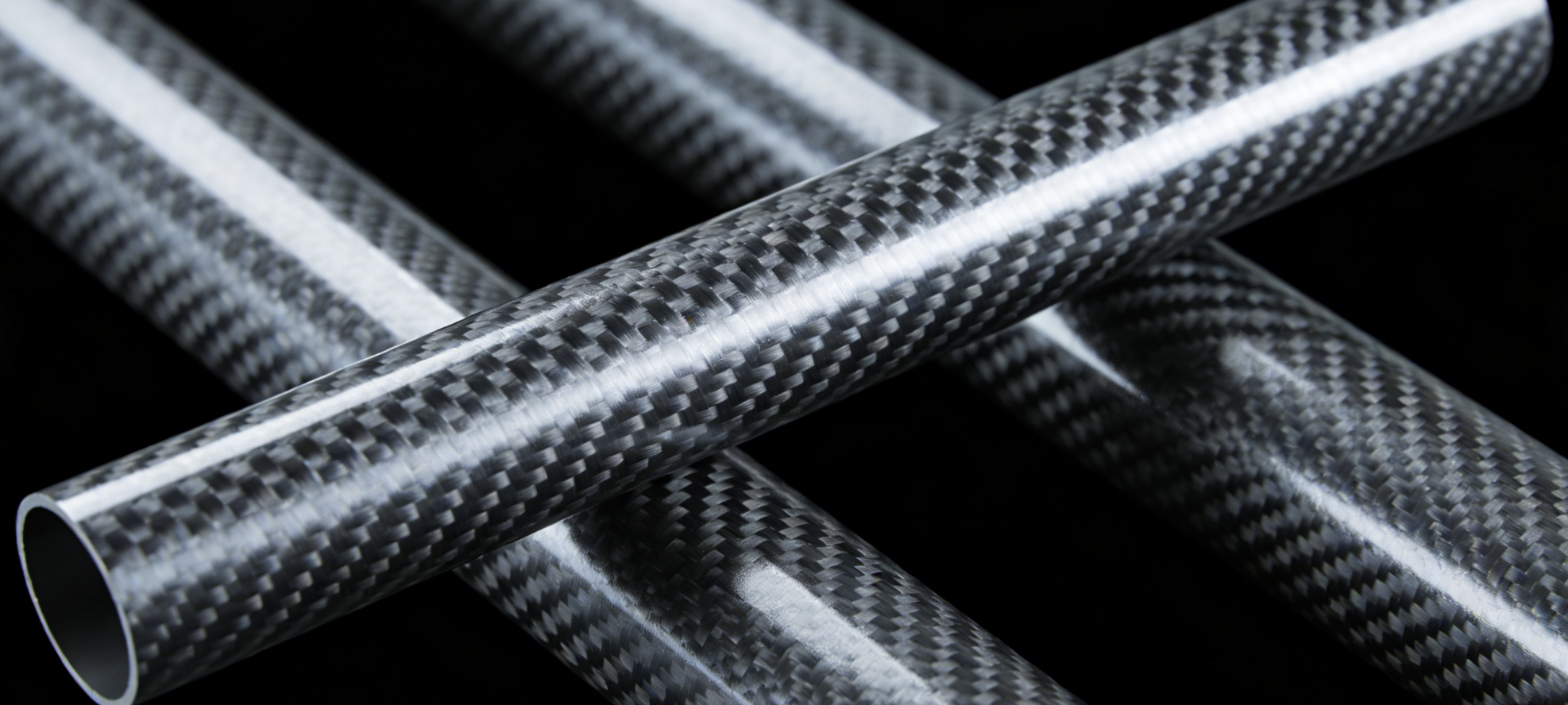
25.4mm is not an accident. This dimension shows up everywhere — drone frames, camera sliders, bike builds, robot joints. It sits at the crossover point between structural strength and low weight. That’s why builders keep coming back to it.
A 1 inch carbon fiber tube with a 1.5mm wall weighs 80–90 g/m. The aluminum equivalent? 220–250 g/m. That’s a 64% weight reduction. Compressive strength runs 5–7x higher too. For engineers picking between materials, those numbers settle the debate fast.
Wall Thickness Options at 25.4mm OD
|
Wall |
ID |
Weight/m |
Axial Comp. Strength |
|---|---|---|---|
|
0.5mm |
24.4mm |
28–35 g |
800–1,200 MPa |
|
1.0mm |
23.4mm |
50–65 g |
1,200–1,800 MPa |
|
1.5mm |
22.4mm |
75–90 g |
1,500–2,200 MPa |
|
2.0mm |
21.4mm |
95–115 g |
1,800–2,500 MPa |
Where This Size Gets Used
-
Quadcopter frames: 850mm with sleeve, fits M3–M5 screws, handles 500g payload
-
Camera sliders: 1000–2000mm rails, M8 end caps, 24mm dolly clearance
-
Robot joints: 1.5mm wall, 23–24mm bore hubs, 5–10 Nm torque rating
-
Bicycle frames: pairs with 22.2–25.4mm ID clamps via carbon sleeves
Stock lengths run from 850mm to 2000mm. Pricing starts at $1.50–$8/pc on 10-piece minimums. That’s low enough to prototype with, and it scales well into production runs.
2 Inch Carbon Fiber Tube (50.8mm OD): Heavy-Duty Applications & Load Capacity
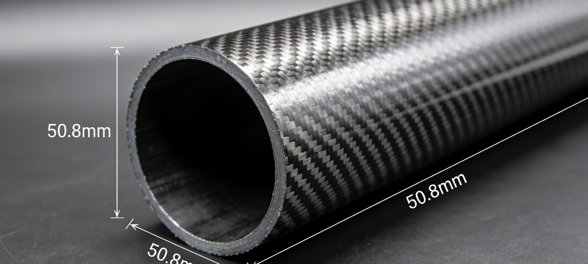
At 50.8mm OD, the 2 inch carbon fiber tube hits a threshold that smaller diameters can’t reach. This is where the material moves beyond being just a component — it becomes structural infrastructure.
The numbers tell the story. Density sits at 1.5–1.6 g/cm³, against steel’s 7.85. That gap gives you 40–70% weight savings in real hardware. Fatigue life runs 5–10× longer than aluminum under cyclic loading. A driveshaft, aerospace beam, or industrial roller needs to survive thousands of load cycles without creep. At this diameter with the right wall thickness, it does exactly that.
Wall Thickness at 50mm OD: What the Spec Table Tells You
|
OD |
ID |
Wall |
Weight (g/m) |
|---|---|---|---|
|
50mm |
48mm |
1.0mm |
236 |
|
50mm |
47mm |
1.5mm |
355 |
|
50mm |
46mm |
2.0mm |
460 |
|
50mm |
44mm |
3.0mm |
650 |
Bending stiffness (EI) at 2.0mm wall: 7,850 N·m². That number matters for any build where deflection under load drives the design outcome.
For heavy-duty structural use, stay in the 2.0–3.0mm wall range (ID 44–47mm). The 1.0mm wall works for light-duty, non-impact use at this diameter — not for demanding structural loads.
Layup Choice Determines Load Capacity
Three layup options cover most heavy-duty builds:
-
Unidirectional (UD): tensile strength up to 1,500 MPa, flexural modulus 150 GPa — top axial capacity for industrial rollers and aerospace beams
-
3K plain/twill weave: 750–800 MPa, balanced multi-axis strength — a solid fit for UAV mast structures and marine members
-
Hybrid carbon/glass: 600 MPa, better impact toughness, lower cost — the right pick where shock loading is the main concern
Safety factors matter here. Static loads need 1.5×. Dynamic and cyclic loads require 2.0×. Impact scenarios push that to 2.0–3.0×.
Where This Tube Belongs
You’ll find it across a wide range of confirmed applications: aerospace instrument supports, robotic arms, automotive structural members, marine equipment, photography and sound booms, and UAV fuselage masts. The round cross-section delivers high torsional rigidity. That makes it the go-to shape for driveshafts and rotating components — a rectangular profile would fail under the same twist load.
Medium Diameter Carbon Fiber Tubes (25mm–80mm OD): Structural Engineering Selection Guide
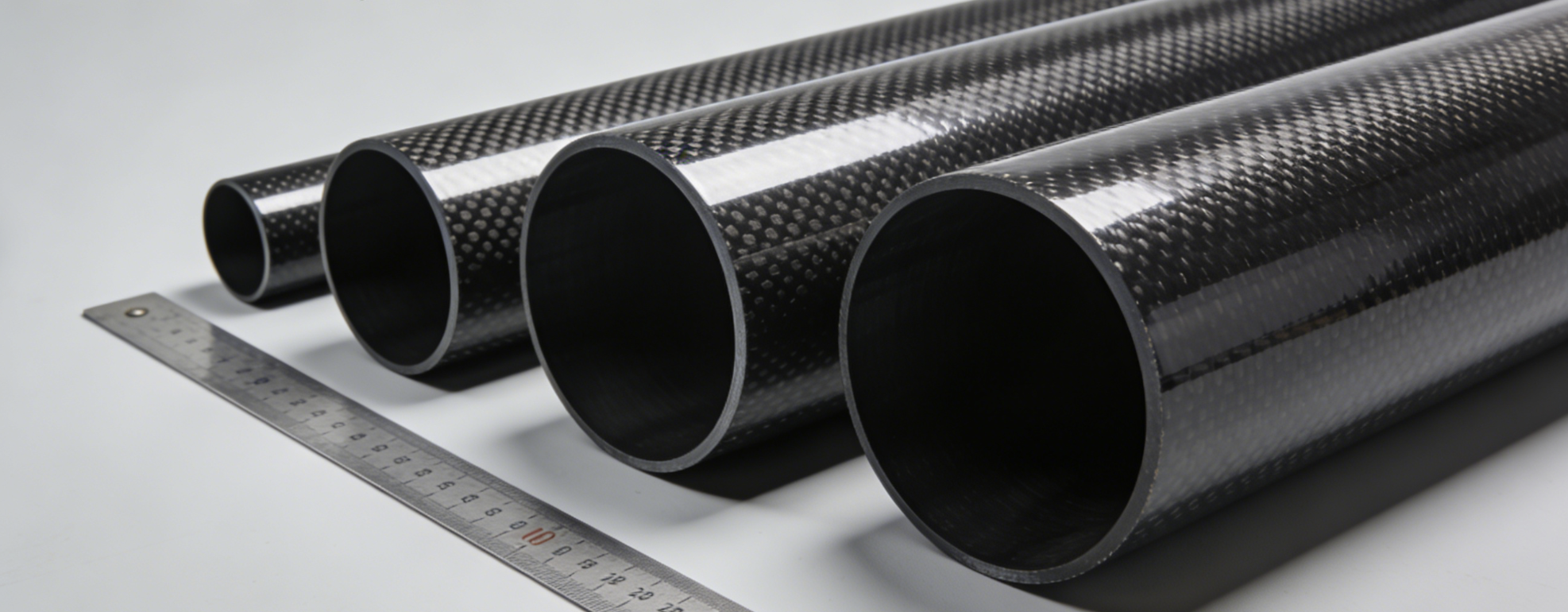
The 25mm–80mm OD range is where carbon fiber stops being exotic and starts being structural.
Density sits at 1.5–1.8 g/cm³ — against steel’s 7.85. That gap tells you why robot exoskeletons, bicycle frames, and automotive driveshafts now specify carbon buis in this band. Weight drops by two-thirds. Specific strength climbs to 1,500 kNm/kg on T800 fiber.
Specs by Diameter Band
|
OD Range |
Wall Thickness |
Typical ID |
Linear Mass |
|---|---|---|---|
|
25–30mm |
1.5–3.0mm |
21–26mm |
120–220 g/m |
|
40–50mm |
1.5–5.0mm |
32–46mm |
220–400 g/m |
|
60–80mm |
2.0–5.0mm |
50–70mm |
400–700 g/m |
Selection Logic by Application
Three applications dominate this range. Each one needs a different priority.
-
Robot exoskeletons: Stiffness comes first. Target E >150 GPa, wall 1.5–2.5mm, linear mass under 200 g/m. Safety factor ×2.0.
-
Bicycle frames: Balance modulus (103–150 GPa), OD 25–40mm at 2.0mm wall. Specific strength runs 3.8× aluminum.
-
Automotive driveshafts: Strength matters more than stiffness here. Use T800 fiber (σ >800 MPa), OD 50–80mm, wall 3–5mm, with a torsion-focused layup.
Quick wall thickness check: t ≥ M / (π r² × σ_allow), where σ_allow = 600 MPa for T300, 800 MPa for T800.
Large Diameter Carbon Fiber Tubes (100mm–248mm OD): Industrial & Aerospace Grade Options
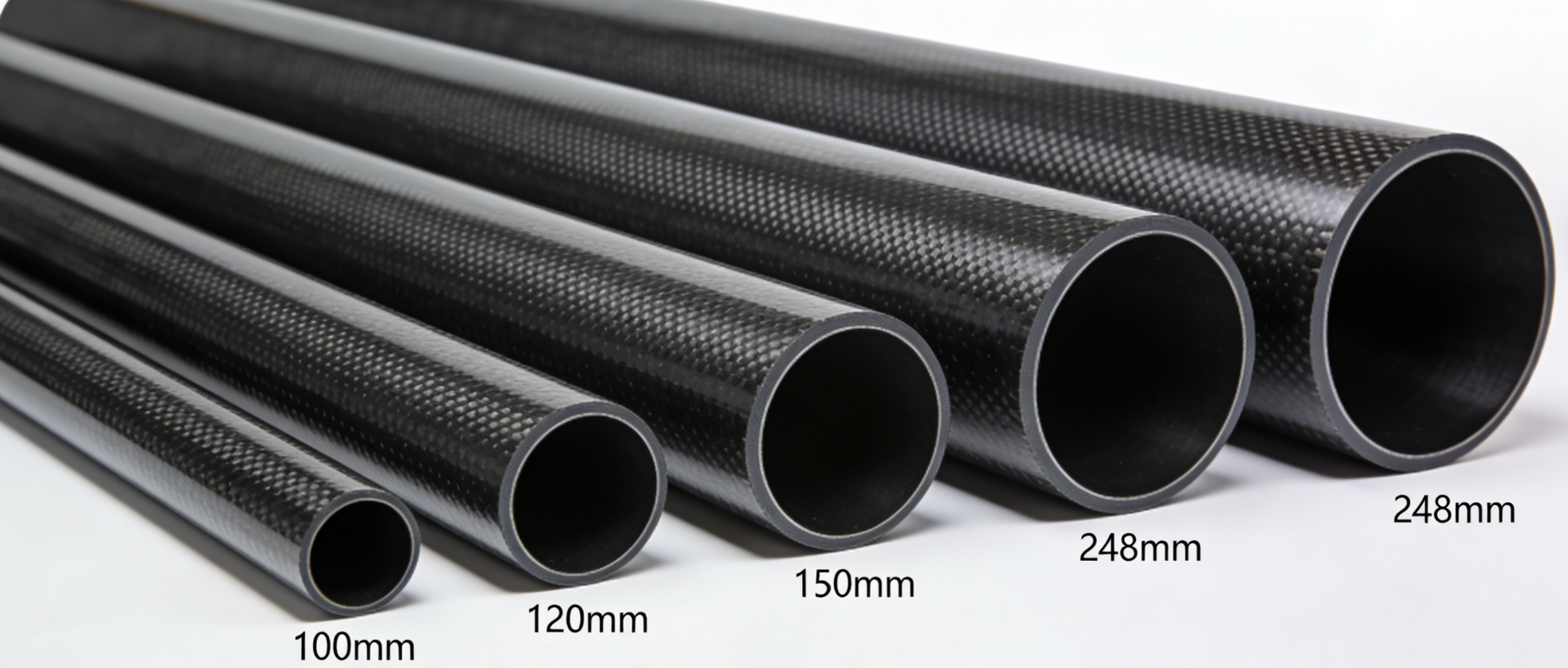
At 100mm OD and beyond, carbon fiber tubes stop being components. They become structure.
Density sits at ~1.44 g/cm³ — steel runs 7.85. That 82% weight reduction is not a marketing claim. You see it on the scale, in the load calculation, and in the fatigue report after 10,000 cycles.
The standard range covers 100mm to 248mm OD, with lengths up to 2,438mm (96″). Wall thickness steps up in 1mm, 1.5mm, 2mm increments — going up to 10mm on custom orders. Each step builds on prepreg layers of ~0.15mm. This gives you precise stiffness control with no guesswork.
What This Size Range Gets Used For
-
Wind turbine blade webs: structural load-bearing under sustained cyclic stress
-
Industrial CT scanner frames: vibration damping at ±0.010″ precision positioning
-
Aerospace fairings: weight-critical housings where every gram carries a cost
-
Optical equipment mounts: thermal stability across 0–200°C operating range
Material grade: T700 carbon fiber with epoxy resin. You get 3K, 6K, or 12K weave options in plain, twill, or unidirectional. Fiber orientation runs at woven 0/90, or we can do a custom layup adjusted to your specific load case.
Need longer runs? Tubes connect via internal or external ferrules — clean, solid joints. For larger orders, we also supply custom one-piece lengths.
Wall Thickness Selection Guide: From 0.3mm Thin Wall to 10mm Heavy Duty
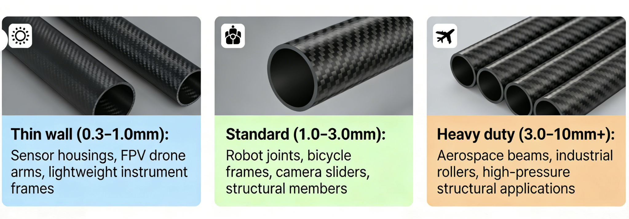
Wall thickness decides everything. It’s the one variable that determines whether your carbon fiber tube handles its first real load — or fails under it.
Three categories cover the full range:
-
Thin wall (0.3–1.0mm): Sensor housings, FPV drone arms, lightweight instrument frames
-
Standard (1.0–3.0mm): Robot joints, bicycle frames, camera sliders, structural members
-
Heavy duty (3.0–10mm+): Aerospace beams, industrial rollers, high-pressure structural applications
Each prepreg layer adds 0.15mm to the wall. That gives you tight, step-by-step control over final thickness. Low-load builds start at 2 layers (0.3mm). Structural parts need 4–6 layers (0.6–0.9mm). Heavy-duty specs go past 20 layers — that’s anything above 3mm.
Fiber angle matters just as much as thickness. 0° orientation adds 50% tensile strength along the axis. ±45° boosts buckling resistance by 30%. 90° hoop plies raise burst pressure capacity by 40%.
For a fast field check, use the D/t ratio. Keep it below 100 to avoid buckling and wall ovality. Heavy-duty builds need D/t < 20. So a 50mm OD tube requires at least 2.5mm wall. That’s what holds tube geometry under real compressive load.
Thin-wall comes with a real tradeoff. Moment of inertia at 0.5mm wall (OD 50mm) sits at just 2.45×10⁵ mm⁴. Step up to 2.0mm wall, and that number quadruples to 9.8×10⁵ mm⁴. Buckling resistance jumps with it — from 1.9×10⁶ N to 7.7×10⁶ N at 1m span.
Carbon Fiber Tube Specifications: OD, ID, Wall Thickness & Weight Reference Tables
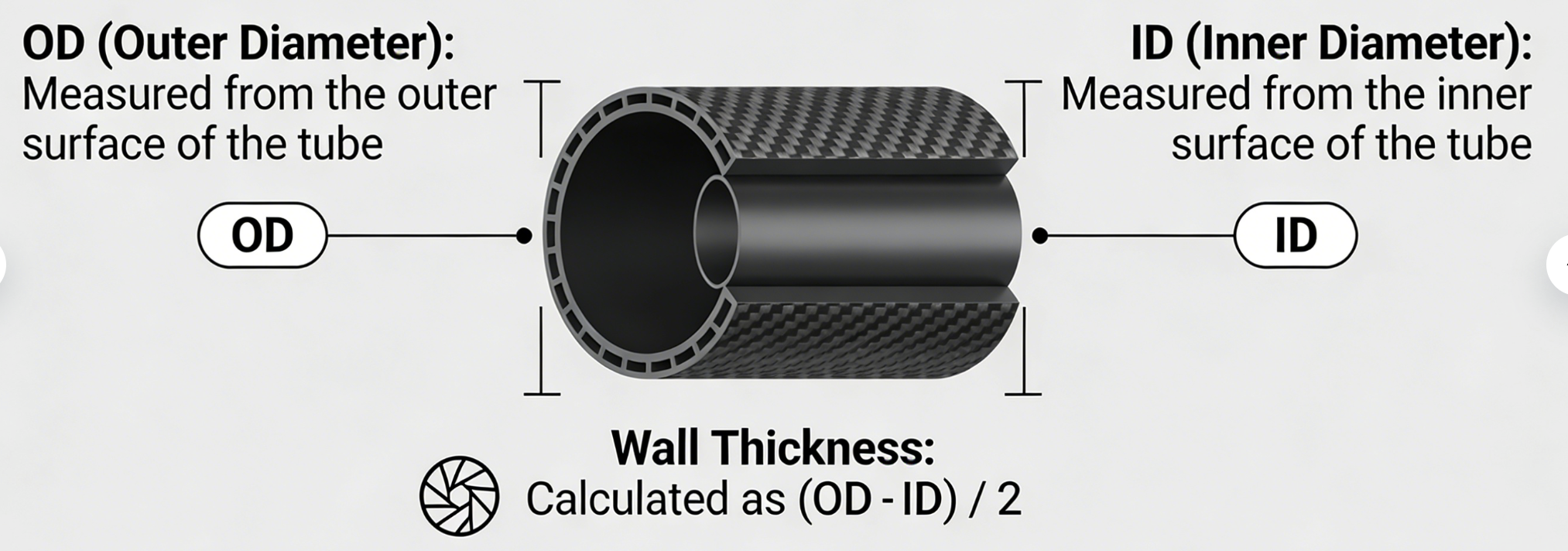
Three numbers define every carbon fiber tube: OD, ID, and wall thickness. Everything else — weight, stiffness, load capacity — flows from those three.
The table below covers the full metric range (T300 epoxy, Vf=60%):
|
OD (mm) |
Common ID (mm) |
Wall (mm) |
Linear Mass (g/m) |
Typical Use |
|---|---|---|---|---|
|
4–6 |
2–4 |
0.3–0.8 |
8–18 |
FPV drones |
|
8–12 |
5–9 |
0.8–1.5 |
25–55 |
Gimbals |
|
15–20 |
12–17 |
1.0–2.0 |
55–110 |
Booms |
|
25–30 |
21–26 |
1.5–3.0 |
120–220 |
Rollers |
|
35–60 |
29–54 |
2.0–5.0 |
250–650 |
Structural arms |
Tolerance Reference
Tighter OD means fewer fitment surprises on the bench:
|
Tube OD (mm) |
OD Tolerance |
ID Tolerance |
|---|---|---|
|
2–5 |
±0.15mm |
±0.15mm |
|
6–30 |
±0.05mm |
±0.05mm |
|
30–100 |
±0.08mm |
±0.08mm |
|
100–300 |
±0.20mm |
±0.20mm |
Length tolerance: ±0.5mm under 2000mm, ±2.0mm beyond.
Material Baseline Properties
-
Tensile strength: 3.53 GPa (512 ksi)
-
Tensile modulus: 230 GPa
-
Flexural strength: 1.81 GPa
-
Density: 1.76 g/cm³
For a 25mm OD tube at 2.0mm wall, bending stiffness EI reaches 2.9×10⁵ N·m². That’s more than double the 1.5mm wall value of 1.8×10⁵. Use these safety factors based on your load type:
-
1.5× for dynamic loads
-
2.0× for impact
-
1.3× for UAV builds, where weight is the main constraint
Custom Carbon Fiber Tube Options: Non-Standard Sizes, Special Wall Thickness & Long Lengths
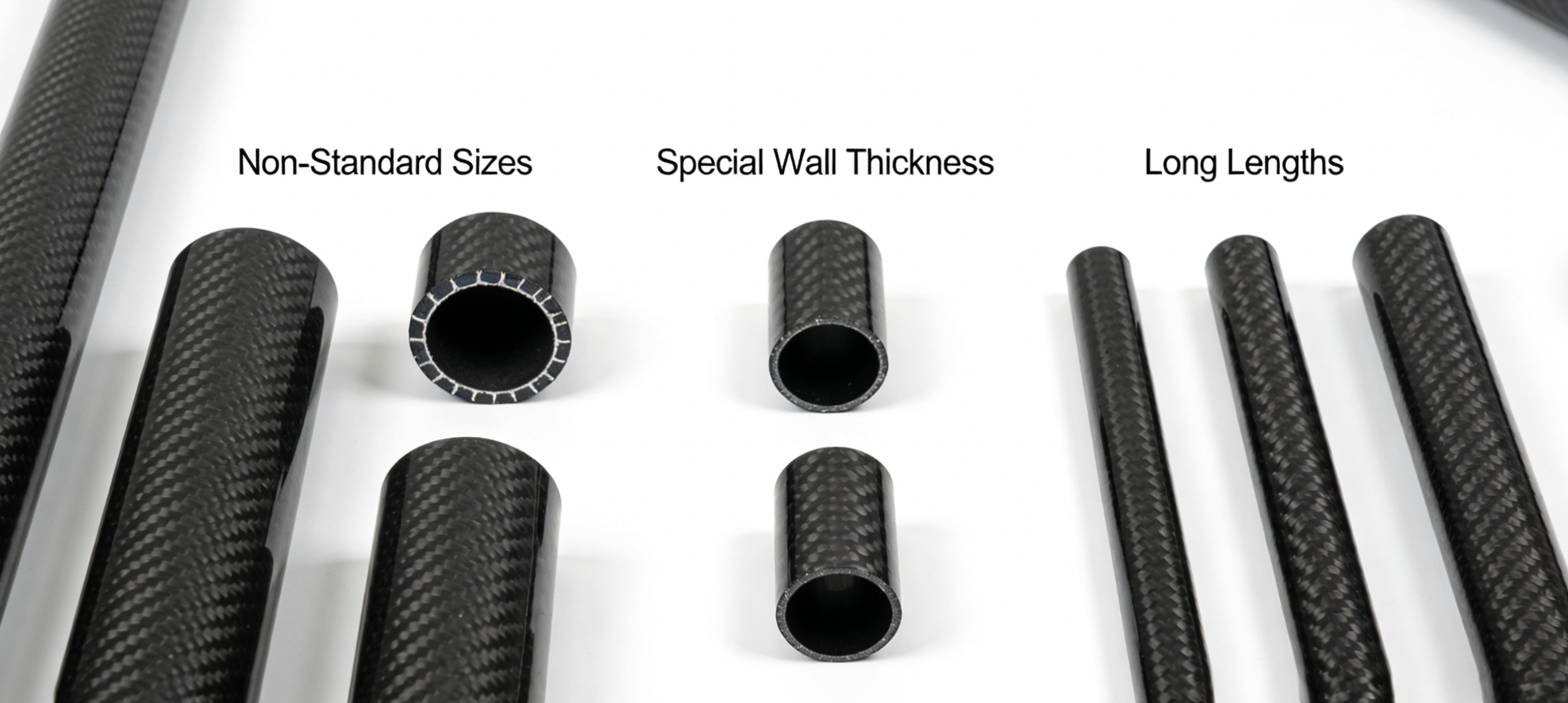
Stock sizes solve 80% of problems. The remaining 20% is where projects either get compromised — or get built right.
Your ID falls outside the 0.250″–3.75″ stock range. Your length pushes past 90″. Your wall thickness needs to hit an exact 0.088″ — that’s 9–10 plies at ~0.006″ per layer. In any of these cases, custom is the path forward. There’s no structural workaround that holds up long-term.
What Can Be Customized
-
Wall thickness: 0.024″ to 0.500″, adjusted one ply at a time
-
Length: minimum 30″, maximum 90″ for custom production; select stock runs to 95″
-
Non-round profiles: oval, elliptical, octagonal, hexagonal — round is not required
-
Fiber modulus: 15–16 msi standard, 20–21 msi intermediate, or 30–32 msi high-modulus carbon
Tooling cost comes down to one thing: whether your mandrel already exists. We stock 100+ proprietary mandrels covering 0″–4″ ID. Most orders skip new tooling fees because of that. Outside this range, a new mandrel is needed — pricing depends on diameter and wall complexity.
MOQ starts at a single tube for existing tooling. Submit your load parameters, tolerances, and surface finish spec. We confirm the drawing first. Prototyping starts from there.
How to Choose the Right Carbon Fiber Tube Size: 5-Step Engineering Selection Process
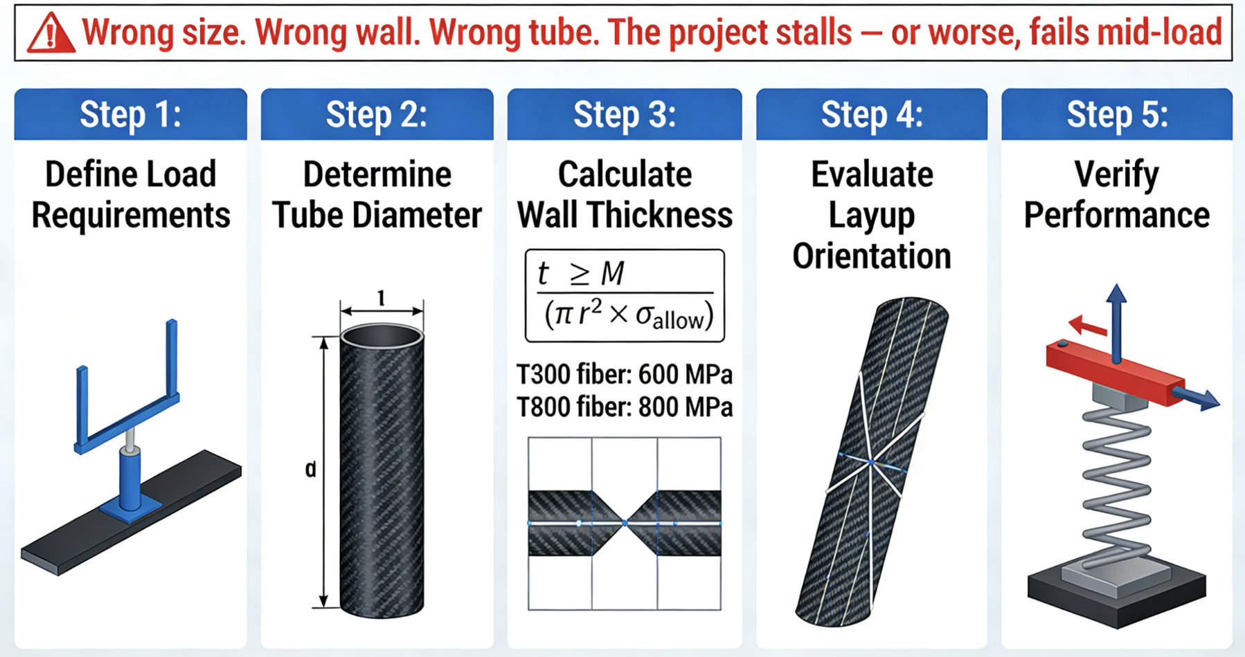
Wrong size. Wrong wall. Wrong tube. The project stalls — or worse, fails mid-load.
Five steps prevent that.
Step 1: Define Your Load Path
Start with three numbers: bending moment M (N·m), torsion T (N·m), and axial force F (N). These aren’t optional inputs — they’re the foundation every other decision sits on.
Use the right safety factor before moving forward:
– Static loads → ×1.0
– Dynamic loads → ×1.5
– Impact scenarios → ×2.0
– UAV/weight-critical builds → ×1.3
A UAV arm rated at 50 N·m? Multiply by 1.3. Size to that number.
Step 2: Select Outer Diameter
A larger OD boosts bending resistance fast. It does more than adding wall thickness — and costs you less mass. Match your OD to the connection interface first. Then optimize from there.
Step 3: Calculate Wall Thickness
Use: t ≥ M / (π r² × σ_allow)
Plug in 600 MPa for T300 fiber, 800 MPa for T800. Thicker walls resist buckling. Thinner walls cut mass. Layup orientation lets you balance both.
Step 4: Choose Surface Finish
-
Matte — grip, low glare, easy visual inspection
-
Glossy — clean aerodynamic look, automotive-grade appearance
-
Raw weave — industrial traction, structural aesthetics
Step 5: Lock In Tolerance Class
-
P1 Aerospace: ±0.05mm OD/ID, straightness ≤0.10mm/m
-
P2 Industrial: ±0.10mm OD/ID, straightness ≤0.30mm/m
Set your tolerance class at the start. It shapes fitment, fabrication cost, and inspection method — all three, at once.
Frequently Asked Questions About Carbon Fiber Tube Sizes
These questions come up in every serious procurement conversation. Here are the answers — with actual numbers, not rough estimates.
Can carbon fiber tubes be cut to custom lengths?
Yes. Use diamond-coated saws or fine-tooth blades. Take your time with each cut to protect wall thickness integrity. Roll-wrapped tubes hold clean edges at custom lengths. Standard stock goes up to 2,500mm. Select sizes reach 5,000mm. Custom production can hit 10,000mm.
What’s the tightest tolerance available?
Standard production tolerance is ±0.1mm for both OD and ID. Precision grades push that down to ±0.010–0.015 inches on inch-dimensioned tubes. Use micrometers or calibrated calipers to measure — not visual guesses.
Can non-standard carbon fiber tube specifications be ordered?
Yes. Here’s the full range we work with:
– Outer diameters: 1mm to 800mm
– Wall thickness: 0.2mm to 10mm
– Fiber grade: T300 to T1000
Your size isn’t on the standard chart? We can still build it.
What is the MOQ for custom sizes?
Prototype quantities start at one piece — as long as existing tooling covers your ID range. Bulk runs follow standard pricing tiers.
Can surfaces be post-machined or bent?
Bending is possible. The minimum bend radius scales with wall thickness:
– 1mm wall → 50mm bend radius
– 3mm wall → 250mm bend radius
– 7mm wall → 1.7 meters bend radius
Check carbon fiber tube dimensions before and after any secondary processing. Dimensions can shift, so verify both ends.
Are carbon buis (carbon fiber tubes) available in European metric standards?
Yes. The full metric range covers Ø1–57mm OD with wall thickness from 0.2–1.5mm. All dimensions follow European procurement standards.
Conclusion
Picking the right carbon fiber tube takes more than a guess. It takes precise engineering matched with the right material knowledge.
Need a carbon fiber tube 12mm OD for a racing drone frame? Scaling up to a large diameter carbon fiber tube for an aerospace structural build? Or tracking down a specific 248mm custom spec that no catalog carries? The size you need is out there. The real question is whether your supplier can hit consistent wall tolerance, back it with verified stiffness ratings, and cut, finish, or customize on demand.
This guide covered the full range — metric, imperial, thin-wall, heavy-duty, standard, and non-standard. You now have the knowledge. The next step is yours.
Don’t let a 0.5mm specification mismatch derail your next project.
Browse the full carbon fiber tube catalog at hyperxcarbon.com — or submit a custom inquiry now. Your exact size is one conversation away.
Contact HyperX Carbon – Your Trusted Chinese Carbon Fiber Partner
Ready to source high-performance carbon fiber materials or custom forged carbon fiber parts from China?
HyperX Carbon is a leading manufacturer with 20+ years of expertise, specializing in aerospace-grade forged carbon fiber, prepreg, tubes, sheets, and lightweight automotive/drone/medical components. We offer:
-
Stable supply chain with premium raw materials (Toray, Mitsubishi, Hengshen)
-
AS9100D certified production for aerospace & UAV applications
-
Rapid prototyping (5-8 weeks) and monthly capacity exceeding 180,000 parts
-
Competitive pricing with 15-18% cost savings on forged carbon solutions
-
Full customization: from T700/T1100G to ultra-high modulus grades
Whether you’re an eVTOL developer, automotive OEM, drone manufacturer, or medical device engineer, HyperX delivers consistent quality, batch-to-batch reliability, and reliable delivery.
Get in touch today for a free consultation, custom quote, or material sample.
📧 Email: [email protected]
🌐 Website: https://www.hyperxcarbon.com/
📞 Phone/WhatsApp: +86 15623270276 (English support available)
Let’s build your next lightweight innovation together – contact HyperX Carbon now and stay ahead in the low-altitude and advanced composites market.