Choosing the wrong carbon fiber manufacturing process costs more than money. It hurts part performance, delays timelines, and leads to expensive tooling rework.
Sourcing structural components for an aerospace assembly, a motorsport chassis, or a high-precision UAV frame? The choice between carbon fiber layup and CNC machining is not a simple one. Each method has real trade-offs — fiber continuity, surface quality, geometric complexity, and unit economics all shift based on your volume, tolerances, and end-use requirements.
Below is a no-fluff technical breakdown of every major layup method — hand lay-up, prepreg layup, and vacuum bagging — compared against CNC machining. Use it to make the right call for your project.
Carbon Fiber Layup vs CNC Machining
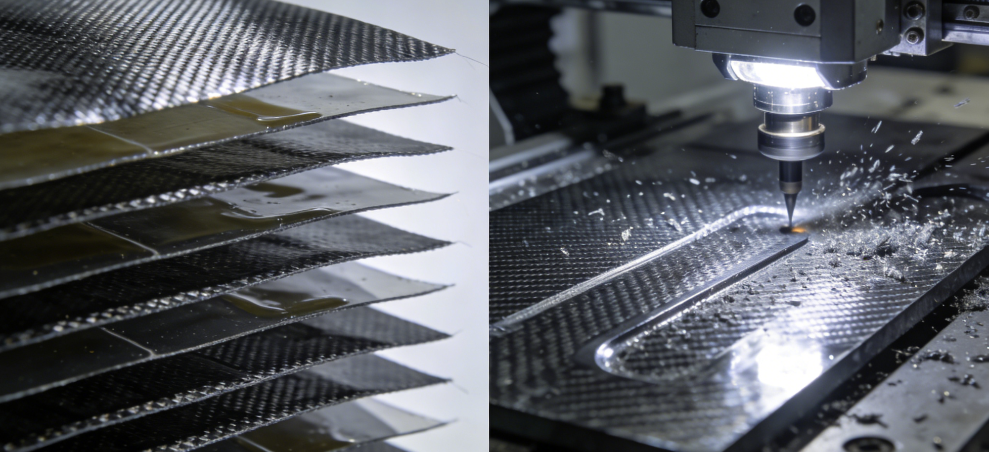
Two processes. Different logic at the core.
Carbon fiber layup builds parts from the inside out. You stack plies, orient fibers, and engineer strength into the laminate — all before any tool touches the surface. CNC machining works the other way. It removes material to hit geometry, achieve tolerances, and create features a layup mold cannot produce.
Neither method is better across the board. What matters is where each one fits best.
|
Aspect |
Carbon Fiber Layup |
CNC Machining |
|---|---|---|
|
Precision |
Layer-dependent |
±0.05 mm on flat panels |
|
Tooling Cost |
Low for 2D shapes |
Diamond/PCD end mills required |
|
Edge Quality |
Epoxy-bonded; clean |
Superior finish, minimal fraying |
|
Best For |
Custom laminates, net-shape parts |
Holes, cutouts, tight tolerances |
The strongest production workflows don’t treat these as competing options. They treat them as a sequence. Laminate first. Machine second. That hybrid approach is where real part performance comes from.
What Is Carbon Fiber Layup? (Core Process Overview)
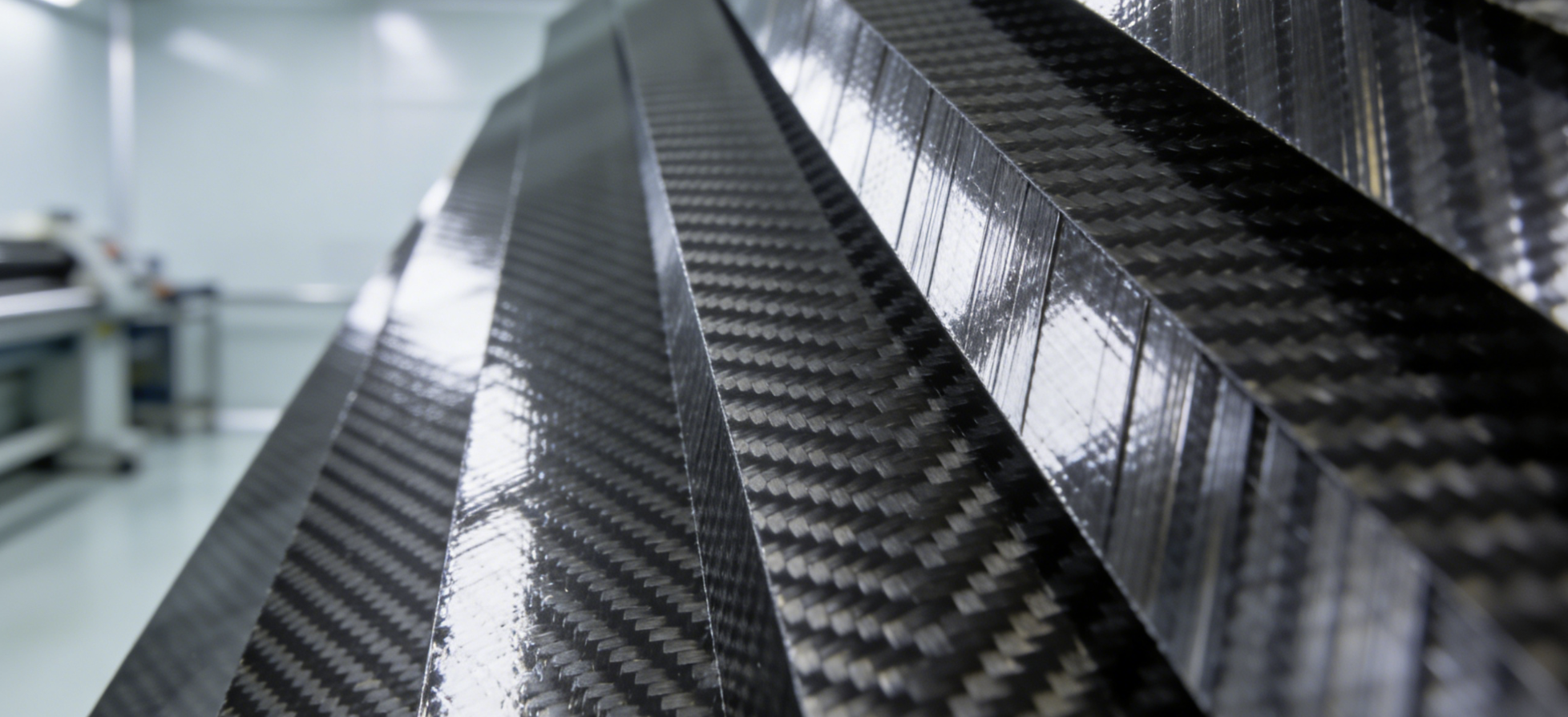
Carbon fiber layup is an additive process — you build a part up, ply by ply, rather than cutting one down.
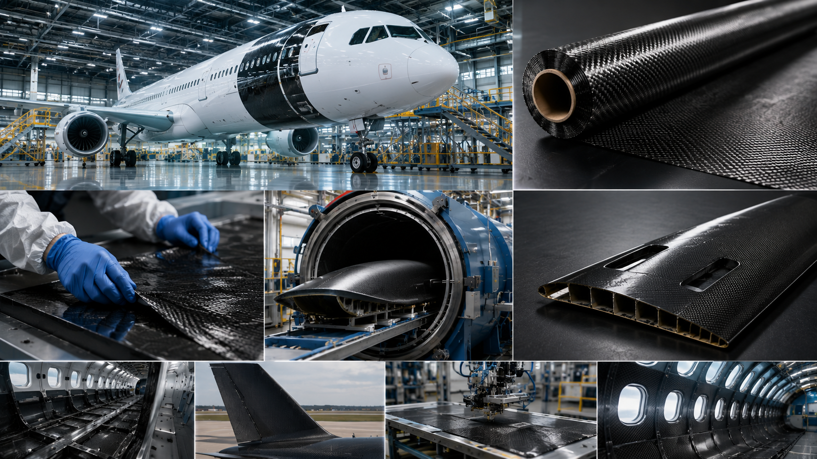
Each layer of carbon fiber fabric or pre-impregnated sheet goes onto a mold at a set fiber angle: 0°, 45°, 90°, or a mix designed for the specific load. Stack enough plies in the right order, add resin, then apply heat and pressure. What you get is a near-net-shape composite structure with strength and stiffness built into its form.
That’s what sets CFRP layup apart from standard subtractive manufacturing. CNC machining cuts away material to reveal geometry. Layup builds geometry from scratch — fiber by fiber, layer by layer — with almost zero material waste.
Three main methods fall under the carbon fiber layup process:
-
Hand lay-up (wet layup) — a worker brushes or rolls resin onto the fiber during lamination
-
Prepreg layup — pre-impregnated sheets come with a factory-set resin-to-fiber ratio, then cure under autoclave pressure
-
Vacuum-assisted processes (VARTM/vacuum bagging) — dry fiber goes under a sealed vacuum bag, and negative pressure pulls the resin through
Each method produces a fiber reinforced plastic laminate with its own mechanical properties, production costs, and quality limits. Your choice of method shapes more than just cost. It drives part density, void content, surface finish, and long-term structural strength.
Hand Lay-Up (Wet Lay-Up): Process, Capabilities & Real Limitations
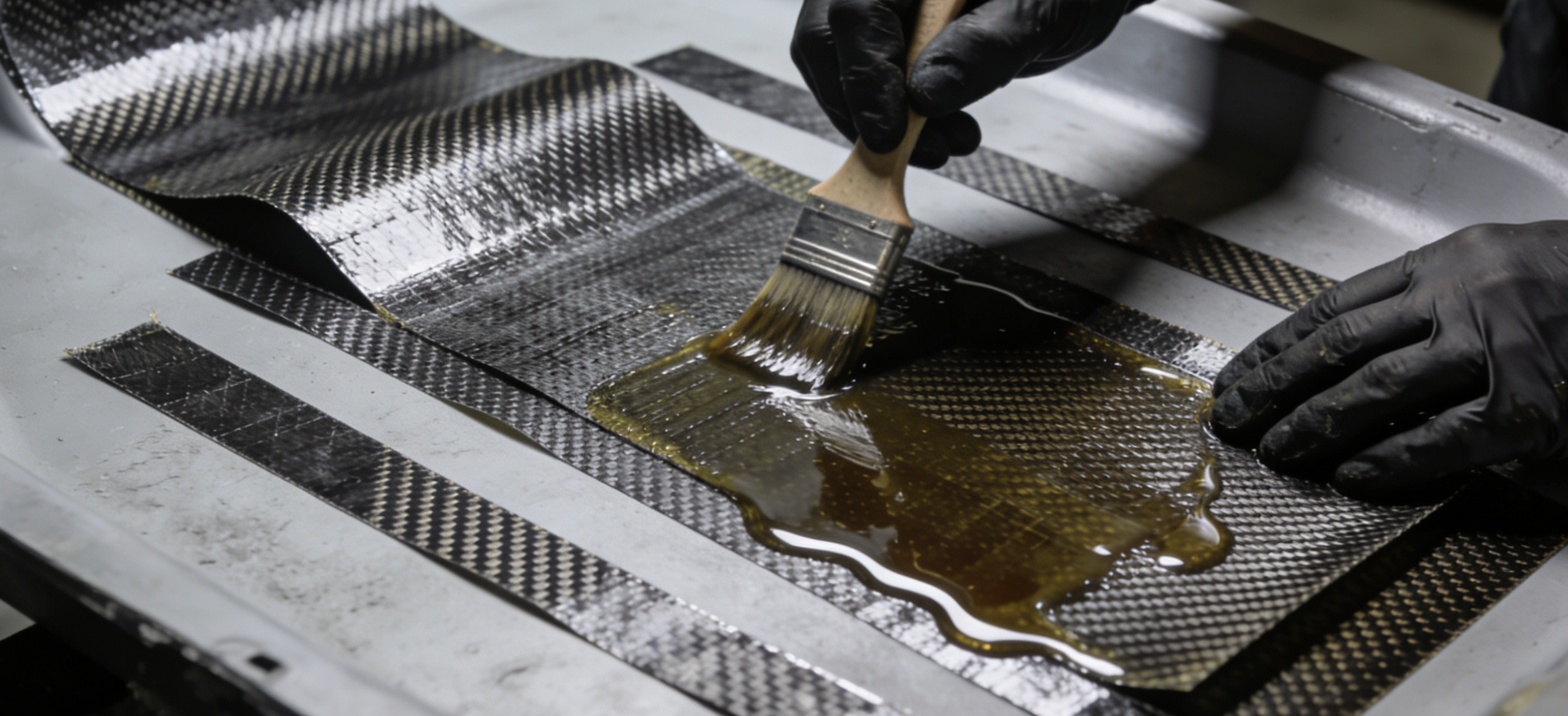
Hand lay-up is the oldest trick in the composite manufacturing playbook — and for good reason. It works.
A worker cuts dry fabric, mixes resin by hand, and applies it to the mold surface with a brush or roller. Layer by layer, each ply gets saturated and pressed down. Squeegees and grooved rollers push out air pockets. No autoclave. No vacuum pump. No complex tooling. Just fabric, resin, and skill.
That simplicity is the method’s biggest strength. It’s also its biggest limitation.
What It Can Do
Fiber volume fractions land between 40–55%. That’s solid for most non-structural applications. The process handles complex shapes well — curved surfaces, variable wall thicknesses, mixed fiber angles. Startup costs stay low. Epoxy and polyester resins cure at room temperature. So you skip the refrigeration, the pressure vessel, and the heavy capital equipment.
This is why hand lay-up shows up in marine hulls, radomes, fairings, carbon tubes, and large industrial covers. These are parts where shape flexibility matters more than tight mechanical consistency.
Where It Breaks Down
Void content runs 1–5%. That number carries real weight. Voids weaken interlaminar shear strength. They create stress concentration points. They raise the risk of failure under sustained load. Aerospace and motorsport parts cannot accept those risks.
The deeper problem is operator dependency. Resin distribution, ply registration, bubble removal — all of it depends on the hands and judgment of whoever runs the layup. One worker’s technique differs from another’s. That gap in skill creates a gap in mechanical performance. Repeatable batch production at any real scale becomes hard to achieve.
For prototypes, repairs, and one-off budget builds, hand lay-up gets the job done. For high-load structural parts or volume production, the process hits a wall fast.
Prepreg Lay-Up: Aerospace-Grade Performance and What It Takes
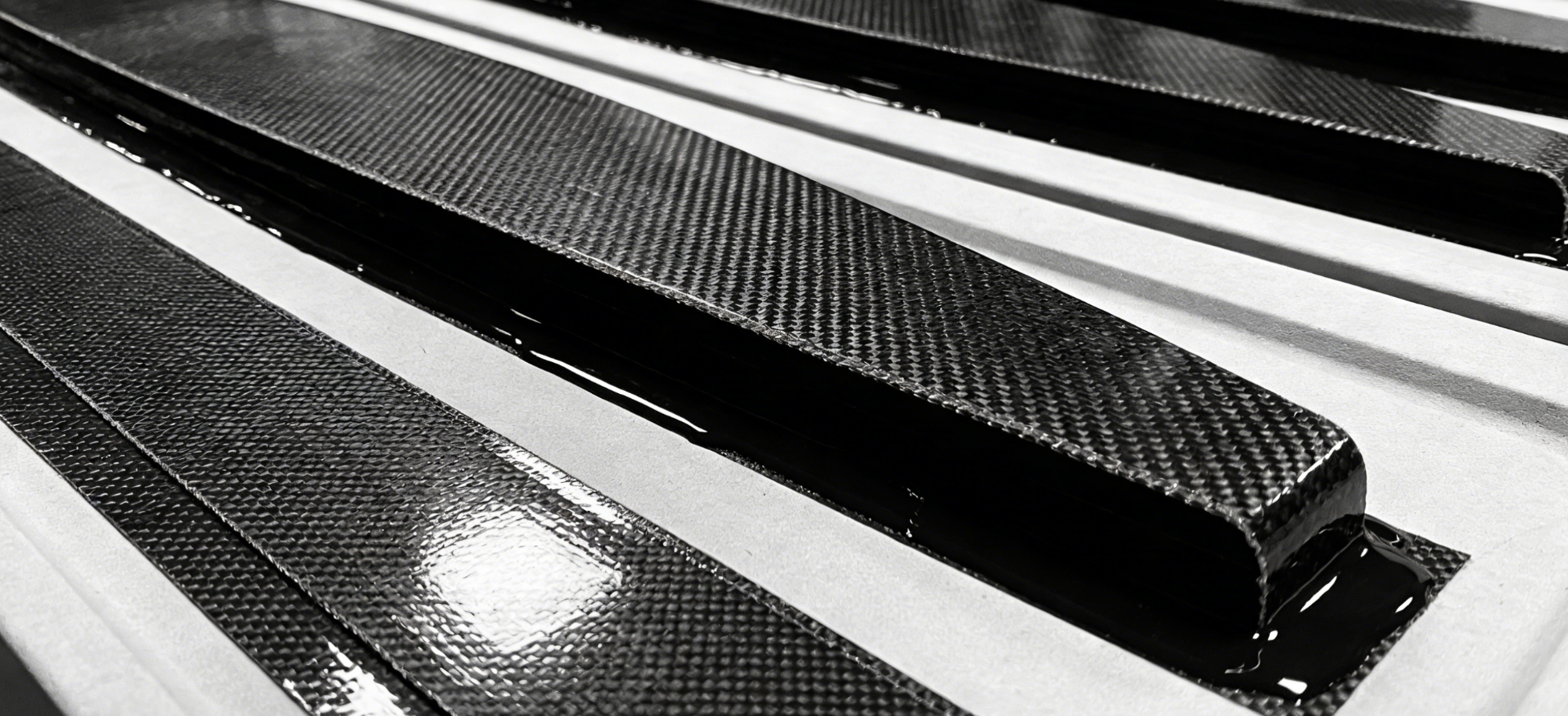
Prepreg isn’t a premium option. It’s a different category of material — full stop.
The fabric arrives pre-loaded with thermoset epoxy resin. It’s factory-controlled, measured to exact ratios, and partially cured to a tacky B-stage state. No mixing on your end. No guessing at ratios. The resin-to-fiber balance is set before the material reaches your hands. That’s why fiber volume fractions hit 55–65% with prepreg. Hand lay-up falls lower and stays inconsistent.
Cold chain storage is non-negotiable. Prepreg lives in -18°C freezers. Leave it at room temperature for a few days and the resin moves past usable state. That freezer is your first infrastructure cost — and it won’t be your last.
The Process Chain
The layup sequence runs like this:
-
Thaw the material from frozen storage
-
CNC-cut plies to exact geometry using automated cutting systems
-
Manual placement — fingertip pressure handles about 80% of ply consolidation
-
Vacuum debulk to achieve full contact between plies
-
Bag encapsulation — bleeder, breather, release ply, and through-bag connectors all go on
-
Cure in an oven or autoclave
That last step is where part quality splits.
Autoclave vs. Oven: The Void Content Gap
|
Parameter |
Autoclave |
Oven |
|---|---|---|
|
Void content |
<1–3%, near-void-free |
Higher voids |
|
Pressure |
Up to 500 psi |
Atmospheric only |
|
Surface finish |
Excellent, glossy |
Moderate |
|
Best for |
Aerospace-grade structural parts |
Lower-volume applications |
Autoclave pressure pushes void content below 1%. That’s not a small step up from hand lay-up’s 1–5% range — it’s a structural performance gap. Prepreg-autoclave laminates carry 10–20% higher fiber volume than wet layup. You get real gains in stiffness, strength, and fatigue life.
That’s why F1 monocoques, aerospace fuselage skins, and high-performance UAV frames run on prepreg. The process produces consistent, certifiable mechanical properties. Hand lay-up and basic vacuum infusion can’t match that level of repeatability.
What It Costs You
Capital requirements are real:
-
Freezer storage for -18°C cold chain
-
Autoclave — large units for fuselage-scale work carry serious capital and operating costs
-
CNC ply cutter for repeatable, exact ply geometry
-
Trained personnel working from engineering placement templates
Per-unit material and processing costs run higher than wet layup. That gap shrinks fast as volume grows and part criticality rises. For medium-to-high production runs with tight tolerances and certification requirements, prepreg’s upfront infrastructure cost becomes the practical economic choice — not a luxury.
Your parts need repeatable resin content, documented fiber wet-out, and OEM or racing certification? Prepreg is the answer. They don’t? You’re paying for performance you won’t use.
Vacuum Bagging: How It Elevates Any Layup Process

Negative pressure does something precise to a composite laminate. At 20–30 inHg across the bag surface, atmospheric pressure becomes a uniform clamping force. It reaches every contour of your part at once — pushing out trapped air and driving fiber compaction in a way no roller or squeegee can match.
That’s the core mechanic. It works on top of any layup method you’re already running.
The System, Broken Down
Five components carry the process:
-
Peel ply — separates from the cured laminate without tearing; leaves a textured surface ready for bonding or painting, no abrasion prep needed
-
Breather cloth — keeps gas moving toward the pump; stops pressure from pooling in dead zones
-
Vacuum bag film — nylon or rubberized plastic; conforms to part geometry without bridging
-
Sealant tape — seals the envelope airtight against the mold edge
-
Vacuum pump — pulls air out and holds compaction through the full cure cycle
What Changes Mechanically
|
Metric |
Conventional Layup |
Vacuum Bagged Layup |
|---|---|---|
|
Fiber Volume Fraction |
Lower, resin-rich |
50–60%, optimized |
|
Voids / Porosity |
High air entrapment |
Sharply reduced |
|
Part Weight |
Heavier |
Lighter — excess resin expelled |
|
Consistency |
Operator-dependent |
Repeatable, uniform pressure |
Fiber volume fraction climbing to 50–60% isn’t just a number. More fiber and less resin means stronger parts at lower weight. That’s the core trade-off composites manufacturing is always chasing.
One thing worth clarifying: vacuum alone doesn’t pull air out of the laminate itself. What it does is stop existing pockets from expanding during cure. Compaction keeps voids small and contained before they can weaken interlaminar strength.
Where It Fits — and Where It Strains
Equipment costs stay low. Bag film, breather cloth, sealant tape — these consumables are all affordable. For small-batch and custom runs, the strength-to-cost return is hard to beat.
The real challenge is labor. Complex geometries need extra hands during bagging. Resin pot-life doesn’t wait while you smooth out wrinkles in the film. Over-bleed creates dry spots. Under-bleed leaves resin-rich zones. Neither issue is fixable after cure.
Vacuum bagging fits best in medium-performance production. It’s a clear step up from open hand lay-up, and a practical choice when autoclave infrastructure isn’t worth the investment.
CNC Machining of Carbon Fiber: Precision Capabilities and Structural Trade-Offs
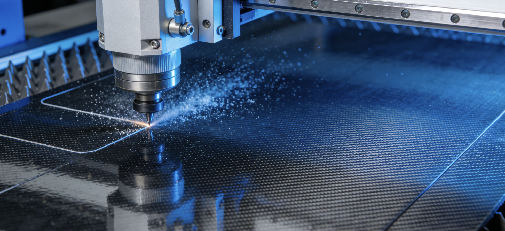
Carbon fiber doesn’t machine like aluminum. It doesn’t forgive like steel. The fibers are abrasive, the matrix is brittle, and the anisotropic structure punishes every wrong parameter choice. Get it wrong and you’re looking at delamination, fiber tear-out, or a cracked edge you can’t fix after the fact.
Done right, CNC machining hits tolerances down to ±0.02 mm. That’s tight enough for aerospace sensor mounts, press-fit interfaces, and assembly-critical holes that require CMM verification and concentricity checks. No layup mold alone gets you there.
What the Machine Can Do
Three variables separate a clean cut from a ruined part: high-speed spindles, low feed rates, and climb milling strategies. Keep RPM high. Keep depth of cut shallow. The heat stays low, and that protects the resin matrix. Push in the other direction and the epoxy degrades at the cut edge. That damage spreads inward once the part goes under load.
CNC handles trimming, chamfering, countersinking, and tapping without issue. One hard constraint: internal corners need a minimum 3 mm radius. Go tighter and chatter builds fast. Cracks start. The part fails before it ever sees a real load.
Tool wear is a real cost factor here. Carbon fiber chews through standard carbide faster than most metal machinists expect. For serious production volume, PCD (polycrystalline diamond) tooling is the right answer. It holds up where carbide gives out.
The Trade-Off Nobody Mentions Up Front
Machining from flat sheet or preform stock generates 70–90% material waste. That number hits you on two levels — cost and structural performance. Near-net layup parts use nearly all the material. CNC from sheet uses a fraction of it.
There’s a structural trade-off underneath that too. Layup builds anisotropic laminates. Fiber orientation gets engineered to carry load in specific directions. CNC machining cuts across that structure and produces isotropic mechanical behavior at the cut surface. You lose directional strength the moment the tool enters the part. For structural applications with defined, critical load paths, that’s not a minor concession — it’s a real design constraint.
Where CNC Belongs in the Process
The strongest production logic uses CNC as a finishing step, not a replacement for layup. Drill after cure. Trim to net edge. Cut holes to final tolerance. That sequence — laminate first, machine second — gives you both the structural efficiency of layup and the dimensional precision CNC delivers.
Dust control is non-negotiable. Carbon fiber particles are fine, abrasive, and hazardous to breathe. Dry cutting with vacuum fixturing and air blast is standard practice. Wet coolant soaks into the fiber-matrix interface and damages it, so shops don’t use it.
Head-to-Head Comparison: Layup Methods vs CNC Machining Across Key Decision Factors
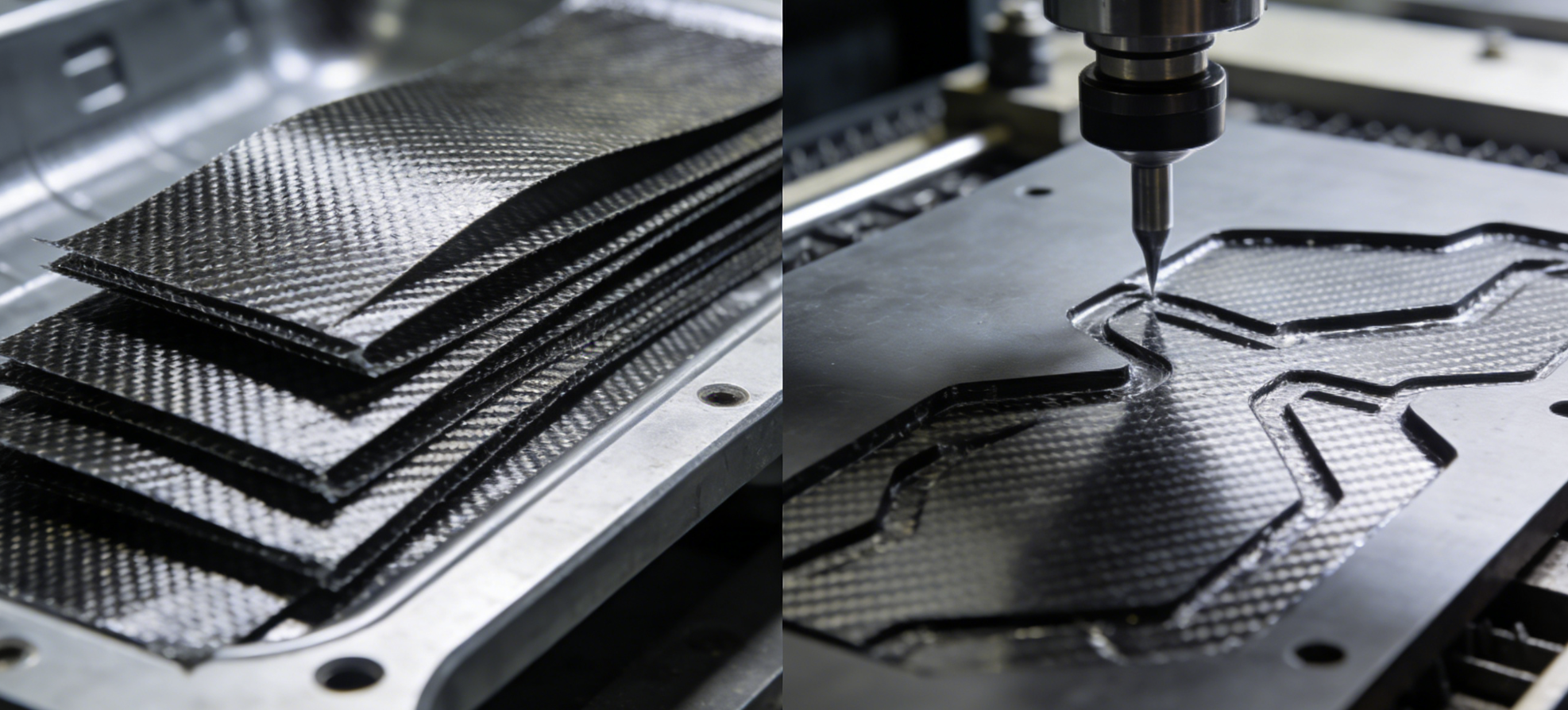
Six variables decide which process wins for your project. Cost, strength, void content, dimensional accuracy, repeatability, and cycle time — each tells a different story based on what you’re building and how many you need.
Here’s where each method stands.
Cost: Tooling, Waste, and the Volume Crossover
CNC carries high upfront machine and software costs. Its subtractive logic burns through material — waste runs 70–90% per part. Labor drops after setup, but you’re paying for everything the cutter removes.
Layup flips that equation. Molds cost less than machines. Material waste stays under 5% per part. The crossover point sits around 100 units: layup unit costs drop over 50% at that volume. Under 50 units on a metal part? CNC skips mold amortization and wins on economics.
Fiber Volume and Mechanical Properties
This comparison runs in one direction. Prepreg layup reaches 55–65% fiber volume fraction — that produces tensile strength around 2.5 GPa in carbon/epoxy systems. Hand lay-up drops to 40–55%, with lower strength output to match. CNC doesn’t build fiber architecture at all. Applied to composite blanks after cure, machining cuts strength by 5–15% through localized heat and edge fracture.
Layup builds performance into load-bearing structural parts. CNC only reduces it.
Void Content and Structural Consistency
|
Process |
Void Content |
|---|---|
|
Hand lay-up |
2–5% |
|
Vacuum bagging |
<1% (60–80% reduction) |
|
ATL prepreg |
<0.5% |
|
CNC (surface) |
±0.0005 in. consistency — bulk voids unchanged |
Internal void control belongs to layup. CNC delivers excellent surface consistency, but that does nothing for what’s happening inside the laminate.
Dimensional Accuracy and Repeatability
CNC holds ±0.0002–0.0005 inches across batches with no human error after programming. Layup comes off the mold at ±0.005–0.020 inches — post-CNC trimming brings that down to ±0.001 inches. Automated layup (ATL) stays under 2% deviation. Hand layup carries ±5–10% variation between operators.
Precision-critical interfaces need CNC. Large curved composites work fine with layup tolerances.
Production Cycle and Geometry
CNC runs in minutes per part at volume, 24/7. A layup cycle — lamination, bagging, cure — takes hours to days for thick laminates. Tight schedules? CNC wins. Your part is a wing skin, fuselage panel, or concave dome? No machine axis can produce those geometries cleanly. Layup is the path forward.
The smartest production logic treats these as a sequence, not a competition. Build the laminate. Then machine the details.
A Decision Framework for Engineers and Procurement Teams
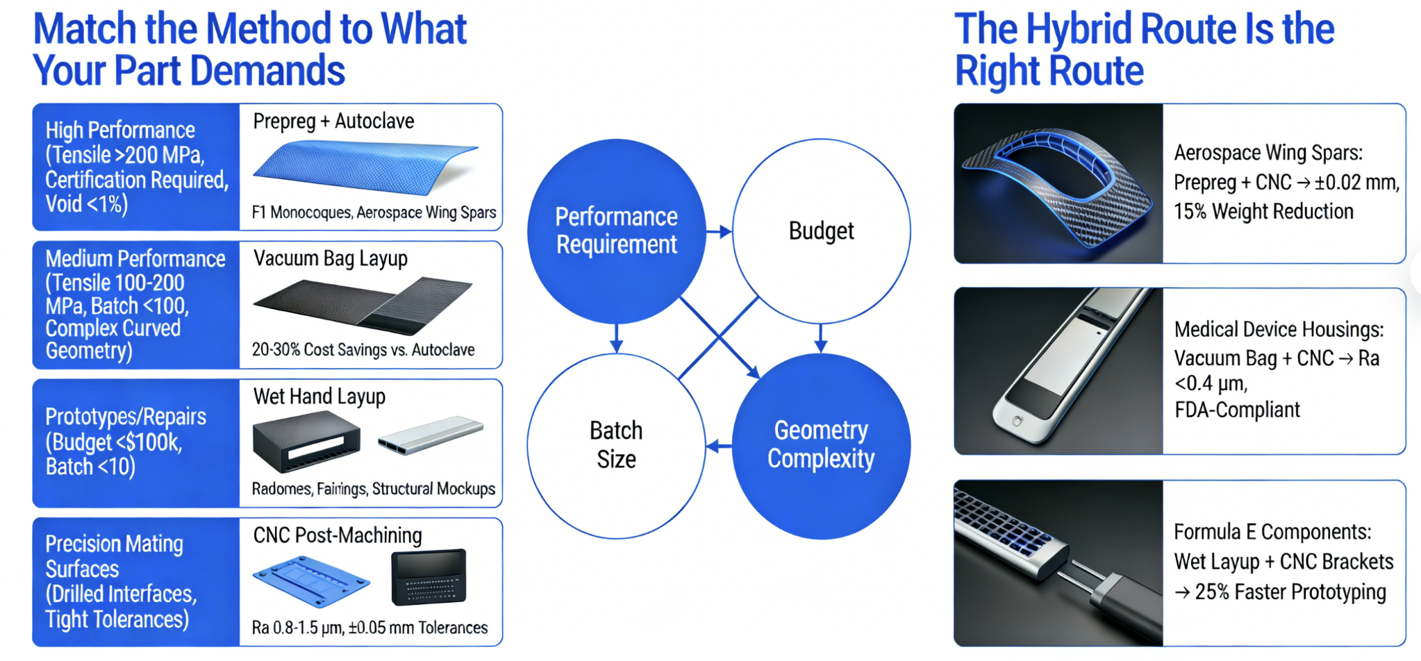
Four variables decide this faster than any spreadsheet: performance requirement, budget, batch size, and geometry complexity. Run those four through the framework below. The right process becomes clear.
Match the Method to What Your Part Demands
High performance, no tolerance for failure — tensile requirement above 200 MPa, certification documentation required, void content under 1%: prepreg with autoclave is the right answer. F1 monocoques and aerospace wing spars belong here. No practical alternative exists.
Medium performance, flexible tooling, cost pressure — tensile in the 100–200 MPa range, batch under 100 units, complex curved geometry: vacuum bag layup. You get 20–30% cost savings over autoclave infrastructure. Structural consistency holds up for non-certified parts.
Prototypes, repairs, budgets under $100k, batches under 10 units: wet hand layup. Setup takes under one day. Material costs run 40–60% lower than prepreg. This works well for radomes, fairings, and structural mockups where mechanical certification is not the requirement.
Precision mating surfaces, drilled interfaces, tight tolerances: CNC post-machining. Surface finish Ra 0.8–1.6 μm. Tolerances held to ±0.05 mm. Use it as a finishing step — not as a replacement for the laminate itself.
The Hybrid Route Is the Right Route
Top-performing production stacks these methods together on purpose:
-
Aerospace wing spars: Prepreg layup + CNC finishing → ±0.02 mm tolerances, 15% weight reduction versus equivalent metal structure
-
Medical device housings: Vacuum bag layup + CNC surfacing → Ra below 0.4 μm, FDA-compliant finish
-
Formula E components: Wet layup chassis + CNC-machined brackets → 25% faster prototyping cycle
Pick your layup method based on performance class. Add CNC where geometry or tolerance demands it. That sequence — not either process on its own — is where structural carbon fiber parts get made.
Frequently Asked Questions
These are the questions engineers ask before signing off on a process decision. Straight answers only.
Is prepreg layup stronger than hand lay-up?
Yes — by a meaningful margin. Prepreg arrives with resin content factory-controlled at 35–40%. That precision feeds straight into mechanical performance. Tensile strength reaches 3,500–5,000 MPa. Interlaminar shear strength lands at 80–100 MPa. Hand lay-up relies on the operator for resin distribution. That inconsistency drops strength output by 15–25%. Void pockets and uneven wet-out are the culprits. Aerospace qualification numbers show this gap clearly — prepreg parts pass at 95%, hand lay-up at 75%.
Can vacuum bagging replace an autoclave?
Not entirely. Vacuum bagging delivers 0.1–0.2 MPa of cure pressure. That’s enough for prototypes and small structural parts. It also cuts infrastructure cost by around 50%. The trade-off is porosity. Vacuum-bagged laminates hold 2–5% void content, and that voids out 10–15% of strength. Autoclave pressure runs 0.5–1.0 MPa, paired with uniform elevated temperature. That combination drives porosity below 1% and delivers 100% of the designed structural value. For flight-critical parts like wing spars, nothing else gets you there.
Does CNC machining cause delamination in carbon fiber?
It can, but you can control the risk. High-speed cutting generates localized heat between 200–400°C. The resulting shear stress pushes delamination risk into the 20–30% range on unoptimized setups — dry fiber laminates are hit hardest. Set feed rate to 0.05–0.1 mm/rev and spindle speed to 10,000–20,000 RPM. Switch to diamond-coated tooling. Those three changes bring failure rate below 5%. Add post-machining ultrasonic inspection to catch what visual checks miss. On well-run production lines, repair rate stays under 2%.
What’s the most cost-effective process for custom carbon fiber parts?
For mid-volume production — 100 to 1,000 units — Resin Transfer Molding (RTM) wins on economics. Equipment investment runs $70,000–$140,000. Per-unit cost lands at $20–50 per gram, about 40% below autoclave production. Automated resin injection keeps scrap below 3%. Surface finish holds at Ra 1.6 μm. Structural performance reaches 95% of autoclave-grade output.
For small batches of 1–100 parts, hand lay-up with vacuum bagging is your practical entry point. Tooling runs $1,400–$7,000. Cycle time is 3–7 days per part. Strength output hits 90% of standard values — solid for prototype validation before you commit to volume tooling.
Conclusion
Every carbon fiber project tells you what it needs — you just have to read it right.
Complex organic geometry with structural demands? Layup wins. Tight-tolerance features, drilled interfaces, or machined-in precision? CNC earns its place. The real skill isn’t mastering one process. It’s knowing which one fits your part, your performance targets, and your budget.
Good carbon fiber components and exceptional ones aren’t separated by material alone. The gap comes from decisions made early — before a single fiber is placed or a spindle starts turning. Mold design, process selection, cure method, laminate architecture. These choices define the outcome.
That’s where experience becomes your competitive advantage.
Evaluating carbon fiber layup processes or comparing manufacturing routes for a high-performance application? Don’t guess your way through it. Talk to engineers who’ve run these trade-offs across aerospace, motorsport, and medical programs. They’ve seen what works — and what fails.
Contact HyperX Carbon – Your Trusted Chinese Carbon Fiber Customization Partner
Ready to develop high-performance carbon fiber materials or custom forged carbon fiber parts tailored specifically for your project?
HyperX Carbon is your long-term strategic partner with over 20 years of expertise in advanced composites. We specialize in delivering aerospace-grade forged carbon fiber custom solutions, along with fully personalized prepreg, tubes, sheets, and lightweight carbon fiber structural components for automotive, drone, eVTOL, and medical applications.
We don’t just supply materials — we provide end-to-end customization support:
-
Stable premium supply chain using Toray, Mitsubishi, and Hengshen raw materials
-
AS9100D certified production tailored for aerospace and UAV requirements
-
Rapid prototyping carbon fiber component in just 5-8 weeks, with monthly capacity over 180,000 parts
-
Competitive pricing with 15-18% cost savings on forged carbon solutions
-
Full customization flexibility: from T700 and T1100G to ultra-high modulus grades, with tailored layups, finishes, and performance specifications
Whether you’re an eVTOL developer, automotive OEM, drone manufacturer, or medical device engineer, HyperX Carbon delivers bespoke material selection, structural optimization, and manufacturing solutions that match your exact technical and performance needs — with consistent batch-to-batch quality and reliable delivery.
Get in touch today for a free technical consultation, personalized quote, or custom material samples.
📧 Email: [email protected] 🌐 Website: https://www.hyperxcarbon.com/ 📞 Phone/WhatsApp: +86 15623270276 (English support available)
Let’s co-create your next lightweight innovation together. Contact HyperX Carbon now and stay ahead in the low-altitude economy and advanced composites market.
HyperX Carbon – Not just a supplier, but your dedicated carbon fiber customization expert.