Swapping your factory steering wheel for a carbon fiber upgrade looks complicated. It’s not. You can do this — even with zero experience pulling apart interior panels.
The catch? Airbags and electrical connectors leave no room for error. Do it right, and you get a sharper, lighter wheel that changes how every drive feels. Do it wrong, and you’re dealing with a deployed airbag or a check-engine light that won’t go away.
This guide covers how to install a carbon fiber steering wheel step by step. You’ll start with cutting battery power the right way, work through the hub adapter torque specs, and finish with setup steps for LED display models and heated wheel wiring.
No filler. No assumptions. Just the process, in order — the way it works.
Safety First: Battery Disconnect & Airbag Deactivation
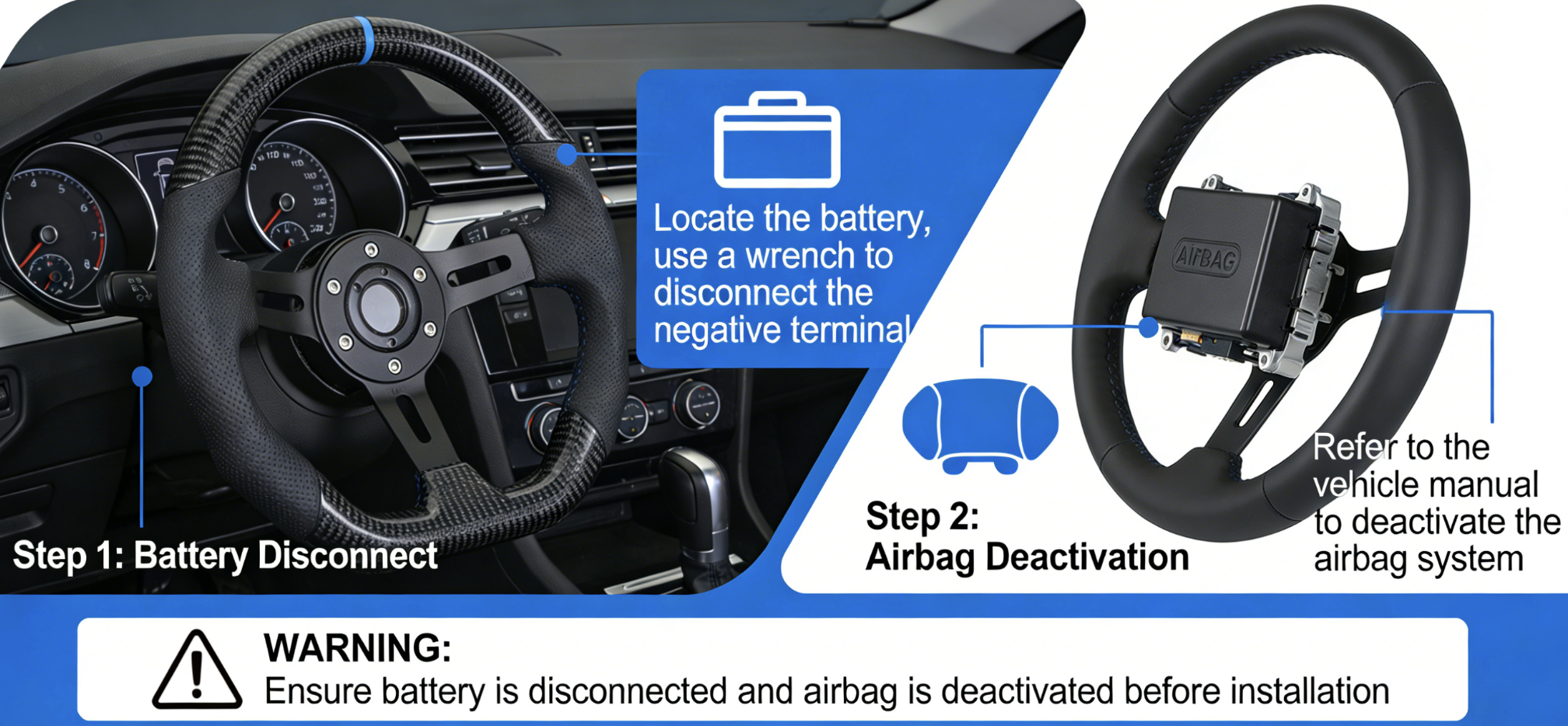
The airbag in your steering wheel deploys in under 0.1 seconds. At the equivalent force of 320 km/h, it can’t tell the difference between a crash and a careless hand with a wrench.
Before touching anything, disconnect the negative battery terminal first — not the positive, not both at the same time. Wrap the terminal in electrical tape. This stops it from brushing against metal and closing the circuit you just opened.
Then wait. Not two minutes. Ten to sixteen minutes.
Here’s why that number matters. Your SRS system stores reserve energy in capacitors. These capacitors are built to fire the airbag even if the battery dies mid-crash. That reserve doesn’t disappear the moment you pull the cable. It drains out over time — and in some systems, it stays active for over ten minutes.
Check that the disconnect worked. Try your headlights. No power means you’re clear to move forward.
One more step most guides leave out: discharge static electricity from your body before touching any airbag parts. Touch bare metal on the car’s frame first. Pyrotechnic igniters react to static. Treat every undeployed airbag like a loaded firearm — that’s what it is.
⚠️ Honda owners: Takata inflator systems are more sensitive than most. Wait the full 10+ minutes. Spontaneous deployment on reconnect is a documented risk, not a theoretical one.
Wheels with integrated ECUs or embedded sensors — like the RSI C6 carbon fiber setup — are not DIY territory. Those systems need SRS load tools, model-specific jumper cables, and current software to reset without issues. Getting it wrong isn’t just a warning light problem. A Dodge Charger SRS reset costs $600+ at the dealer.
Tools & Materials You’ll Need
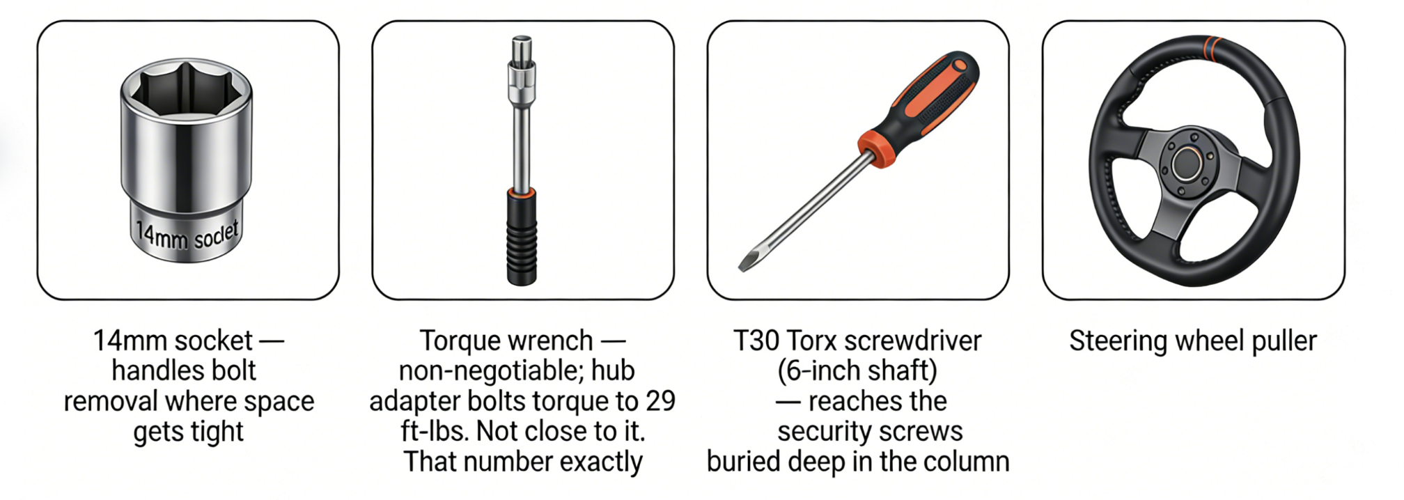
Four tools do the actual work here. Everything else is noise.
The essentials:
-
14mm socket — handles bolt removal where space gets tight
-
Torque wrench — non-negotiable; hub adapter bolts torque to 29 ft-lbs. Not close to it. That number exactly.
-
T30 Torx screwdriver (6-inch shaft) — reaches the security screws buried deep in the column
-
Steering wheel puller — a seized wheel won’t budge by hand. The 3-jaw design grips hub diameters between 28–32mm. It applies up to 1,000 lbs of controlled force.
Skip the puller and you’ll strip threads or yank wires you didn’t mean to touch.
For electrical connections, material choice matters more than most people admit:
Use heat shrink tubing on 70% of exposed connections. It’s waterproof, rated IP67, and seals clean at 90–120°C. Use electrical tape for quick temporary fixes only. Cable ties organize wire looms — they don’t insulate. Overtightened ties cut into harnesses at a 10–15% failure rate.
Need an adapter? Measure your spindle first. An offset over 5mm means you need one. A mismatched bolt pattern does too — 5×114.3 vs 5×120 trips up a lot of truck builds. At that point, the adapter isn’t optional. It’s the whole job.
Removing the OEM Steering Wheel (Step-by-Step)
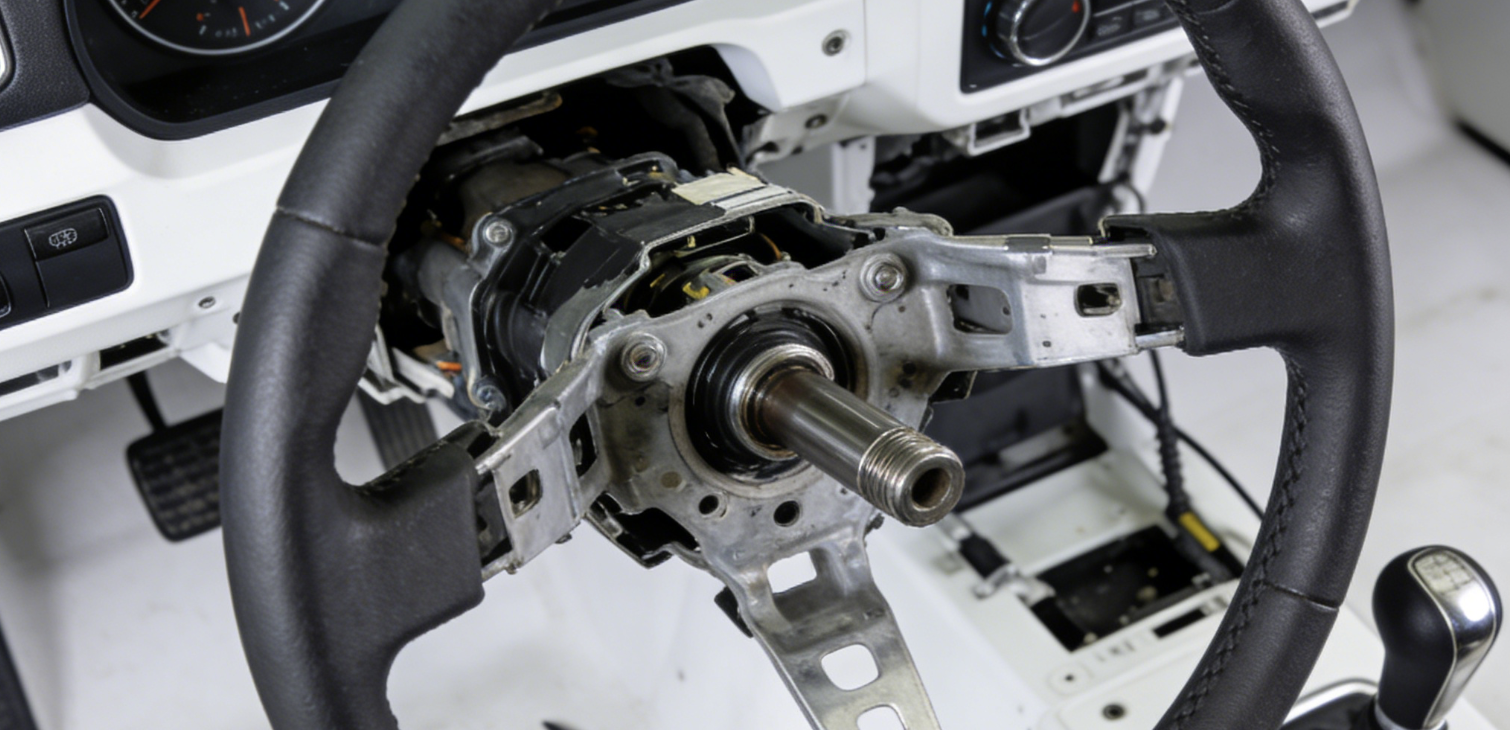
The factory wheel comes off in a specific order. Skip a step or reverse two, and you’re chasing a damaged clockspring or untangling wires you yanked loose.
Here’s the sequence that works.
Before you touch the wheel itself, turn the front wheels straight ahead and leave them there. This isn’t a preference — it’s a requirement. The clockspring is a coiled ribbon connector inside the column. It has a fixed rotation range. Pull the wheel off with the wheels cocked sideways, and you stress that cable before the new wheel even goes on.
Airbag Module Removal
Pry the plastic covers off both sides of the steering wheel. Use a flathead screwdriver in the indent slots. Underneath, you’ll find two T30 Torx screws recessed into the back of the column. Remove them.
Slide the airbag module straight forward off the column. Pull it at an angle and you risk damaging the connectors.
Now the connectors:
-
Yellow sensor connector: Pull down the spring-loaded yellow sleeve. It releases with steady pressure — not force. Yanking it means you’re doing it wrong.
-
Smaller clips: Press inward to release. No tools needed here.
Set the airbag down face-up on a flat surface. Don’t stack anything on top of it.
Center Nut & Wheel Separation
Mark your alignment first. Run a paint pen or nail polish across the wheel spline and the column. That line is your reference. It takes ten seconds and saves you from a steering wheel that pulls left on reinstall.
Nut sizes vary by vehicle: 15/16″ (24mm), 19mm, 21mm, or 14mm — check your model before grabbing a socket. Loosen the nut, but leave it threaded on. That’s on purpose. It keeps the wheel from flying off when the taper breaks.
Lubricate the puller’s pressure screw first. Place the puller bolts into the wheel holes at equal spacing. Thread the center bolt in by small turns. Let the tool do the work. The taper breaks with steady pressure — a hammer has no place here.
Once the wheel frees, remove the puller and unthread the nut. Lift the wheel straight off. Feed the wiring through as you go.
Clockspring: The One Thing You Can’t Undo
Keep the white ribbon cable aligned and straight through the entire removal. Don’t rotate it. Don’t pull it tight to check for slack. Don’t twist it.
That cable carries signals for your horn, controls, and steering angle sensor. Damage it here, and you’re facing a replacement job that costs more than the carbon fiber wheel itself.
Pull the wiring through the column opening now — before reinstall prep. Threading it blind later wastes time and adds risk.
🔧 Reinstall note: The center nut torques to 45 Nm (33 ft-lbs). Hold onto that number for when the new wheel goes on.
Hub Adapter Installation & Alignment
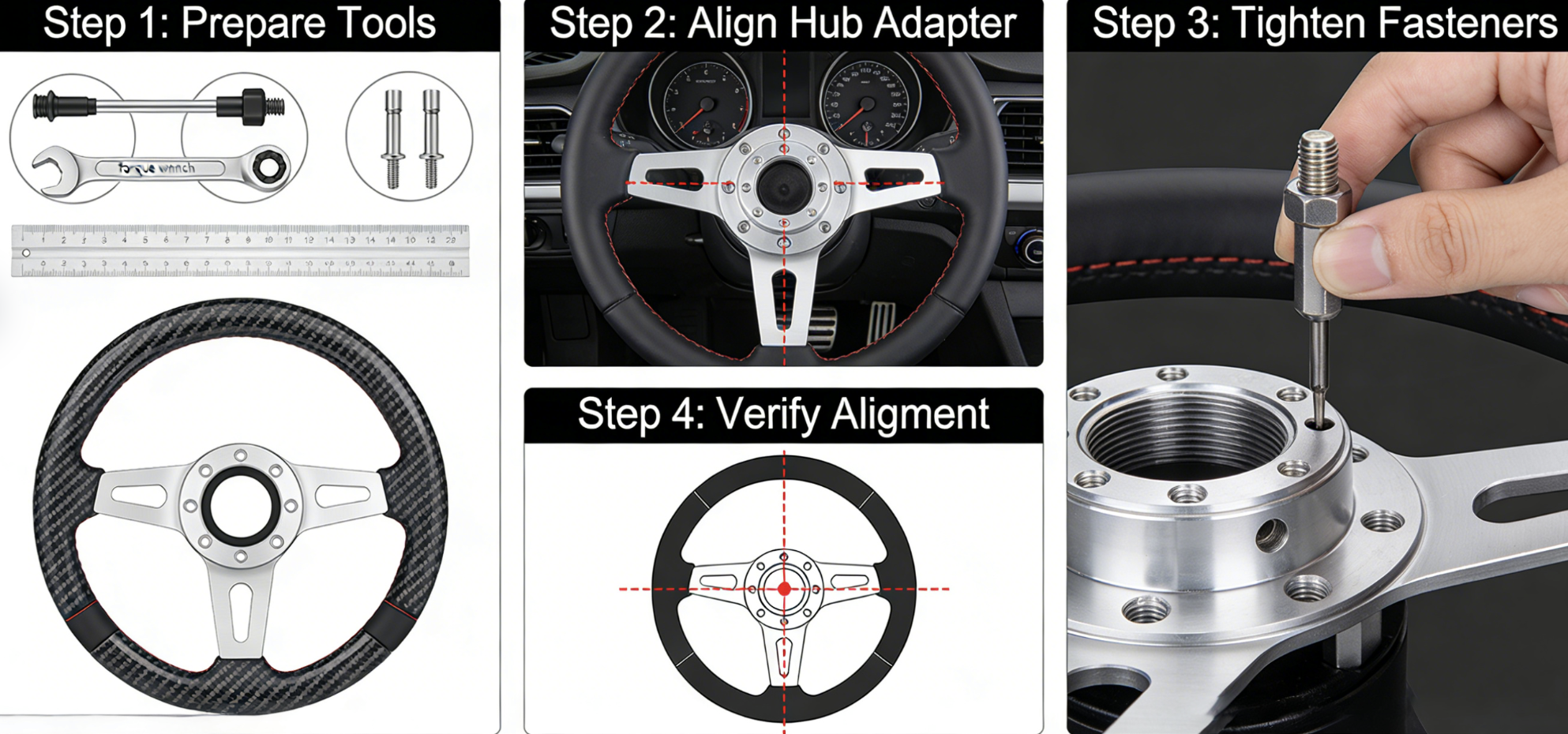
A misaligned hub adapter is why your steering wheel pulls left after a clean install. The fix itself isn’t complicated — the order of steps is.
Start by mounting the adapter plate to your vehicle’s hub. Use at least two lug bolts seated in the elongated holes. Position the plate parallel to the wheel face. Then line up its center hole with the hub center. Next, insert the cylindrical adapter body. The first end connects to your alignment instrument. The second end drops into the plate center hole. Lock it down with the nut and washer.
Here’s where people rush and pay for it later.
Torque the wheel and adapter lug bolts to 100 ft-lbs. Do it in a star pattern, in multiple passes. Not one sweep around the clock. Star pattern. Multiple passes. That’s the difference between bolts that are just seated and bolts that are actually secure.
Getting the Alignment Right
Once the adapter is mounted, lay a straight edge across both hubs. Don’t rotate them. Check the outer edge for any offset. Go past your vehicle’s parallel tolerance spec, and you realign before touching anything else. An offset here causes vibrations you’ll feel at 60 mph. Your steering wheel ends up sitting two degrees off-center — and you’ll notice every time you drive.
The adapter uses an expandable sleeve that self-centers to your alignment head. Direct hub mounting cuts out the run-out errors that clamp-style methods create. The result is clean and simple: wheel centered to adapter, adapter centered to hub. No wobble, no vibration, no callbacks.
Hub adapter torque reference:
|
Component |
Torque Value |
|---|---|
|
Hub adapter flats (HUB-QD) |
25 ft-lbf (34 Nm) |
|
Wheel/adapter lugs |
100 ft-lbs, star pattern |
Honda builds on 4×100 bolt patterns need hub-centric adapters matched to OEM spec. A straight swap to 5×114.3 without hub-centric fitment puts in the exact offset that leads to misalignment. Pickup trucks follow different rules. Medium-duty steer hubs run 150 ft-lbs inner / 100 ft-lbs outer. Anything 1100-size and up requires an interference fit.
Get the torque right, confirm your straight-edge offset, and the adapter is done.
Installing the Carbon Fiber Steering Wheel
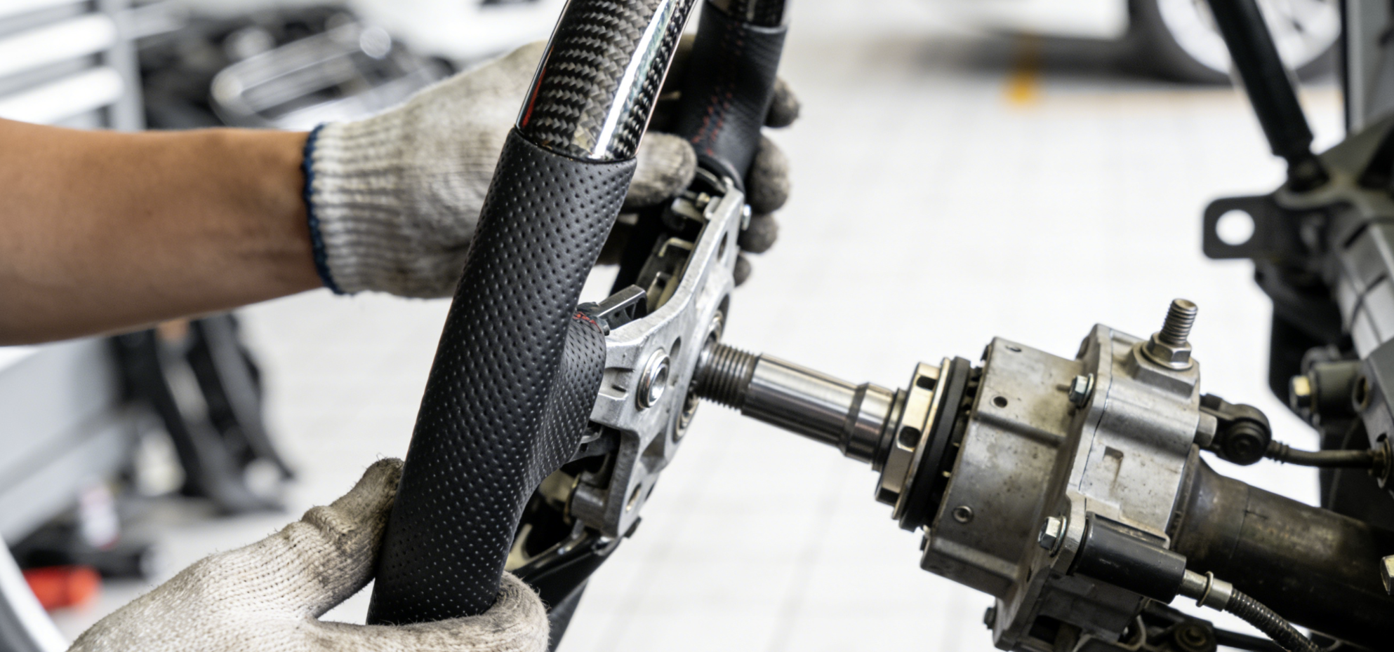
The new wheel goes on in one direction. Get the sequence wrong and you’ll spend an afternoon undoing it.
Thread the 14mm bolt through the center of the steering column. Fit your torque wrench with the 14mm socket. Stabilize the wheel with your free hand. Apply steady pressure until you hear the click. That click isn’t random — it confirms you’ve hit 29 ft-lbs. The wheel is seated. The sensors are aligned. Stop turning right there.
Airbag Module Reinstallation
Slide the airbag back toward its mounting points. Don’t seat it yet. First, reconnect the sensor connector underneath — push it in until it clicks. That click matters just as much as the torque one. A connector that’s 90% in will trigger an airbag warning light within a day of driving.
Connector confirmed? Align the module flush with the mounting points. Run both T30 Torx bolts back in from the side. Replace the retaining clip. The module should sit flat with no gap at the edges.
Wiring: LED Displays & Heated Wheels
LED display models give you two power source options: an ignition-switched 12V feed through the OBD-II port, or a fuse tap connection. Either works. What doesn’t work is a noisy or unstable power feed. Erratic display behavior traces back to the power source — not the display itself.
Route cables behind the trim panels using zip ties. Keep them clear of moving parts and anything that runs hot.
Heated wheel wiring needs one extra step. Cut the plug from your original heater harness. Leave enough wire length on both sides to work with. Match those wires to the corresponding leads on the new wheel. Solder them or use crimp connectors — not tape. Cover every connection with heat shrink tubing before closing anything up. Check polarity too. Reversed wires don’t just kill the heater — on some vehicles, a wrong heater circuit fires a warning light on reconnect.
Post-Installation Checks
Reconnect the positive terminal first, then the negative. That order matters.
Run through the full check before calling this done:
-
Horn — press it. Response should be instant.
-
Steering wheel buttons — test each one
-
Airbag system — no warning lights after 60 seconds
-
Heated wheel — activate and confirm warmth
-
LED display — power on and check responsiveness
A warning light that shows up and clears on its own points to a connector that’s 90% seated instead of 100%. Pull it, reseat it, test again.
Reconnecting the Airbag & Electrical Testing
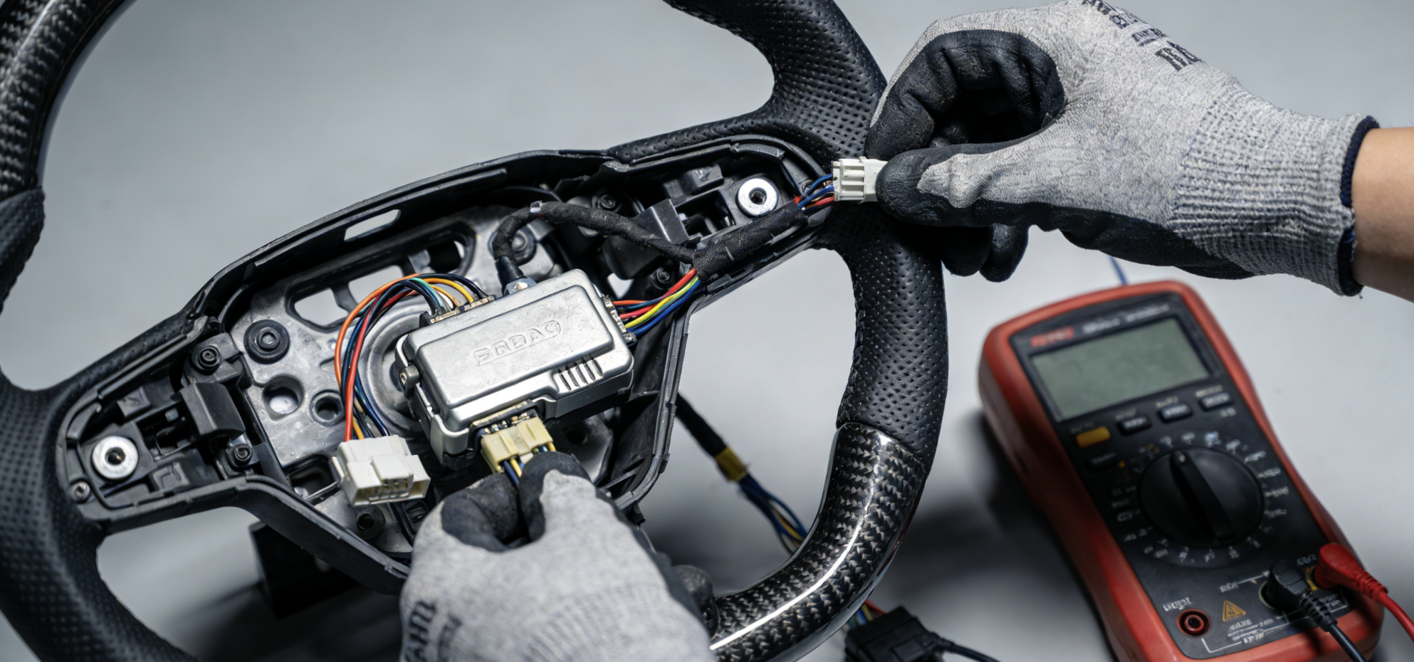
Three things must happen in order when the airbag module goes back in. Power plug first. T30 bolt second. Clips last. This order stops the module from shifting after power-up. Even a small shift can cause real problems.
Discharge static from your body before touching any connector. Touch the door latch. Install your simulators before reconnecting the battery. Testing live circuits without a simulator can trigger an airbag deployment instead of just checking the wiring.
Resistance Checks That Tell You Something
Every circuit in the SRS system has a threshold. Know these numbers before you test anything:
-
Wiring lines to detonator: ≤ 0.5 Ω
-
Individual lines to detonator: ≤ 0.5 Ω
-
Ring (spiral cable) circuits: ≤ 0.5 Ω — disconnect both the airbag and control unit, bridge the terminals, then shake the ring by hand while reading. Resistance that changes means you replace the ring. Reseating it won’t fix it.
-
Belt pretensioner circuits: Check the control unit pins for continuity. No short-to-ground? Verify the full harness run.
One rule covers everything: never measure across the detonator. A direct measurement can push enough current through to activate the squib. That’s why the VAS 5056 simulator exists — use it every time.
Reading the Airbag Warning Light
Turn the ignition on. The airbag light should flash for a moment, then go dark. On, then off — that confirms the system ran its self-check and found no faults.
The light staying on points to one of four causes:
-
Circuit resistance above 2 Ω in the airbag wiring
-
An intermittent ring fault (resistance climbing past 0.5 Ω under movement)
-
A connector seated 90% instead of 100%
-
Unerased crash codes still stored in the control unit
Scan for codes before pulling anything apart again. A stored code takes you straight to the fault. Without one, you’re guessing.
LED Display & OBD Module Setup (For RSI c6 / TESERY Models)
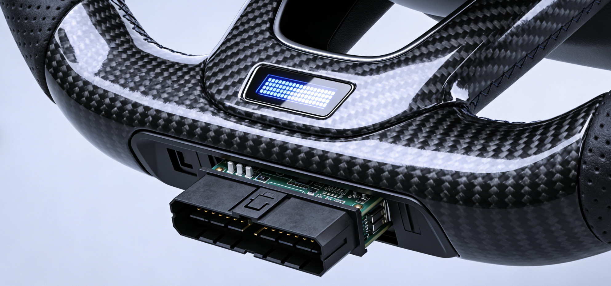
The RSI c6 and TESERY steering wheels pack more technology than most dashboards. That’s the whole idea — but it means the install isn’t done once the wheel is bolted on. The display needs power. The OBD module needs a home. And the pairing process has one sequence that works. Follow it in order.
Choosing Your Power Source: OBD-II vs. Fuse Tap
Two options exist. Pick the one that fits your situation, not the one that sounds more technical.
OBD-II port power is the faster, cleaner choice for most people. Plug it in, get stable ignition-switched 12V, no wiring cuts, no fuse box work. Want something you can remove without a trace? This is it. Tuck the cable under the dash and leave it.
Fuse tap suits the OEM-look crowd — no visible OBD connection, power pulled straight from the fuse box. The tradeoff is real. You’re pulling and adding fuses. That creates short-circuit exposure the OBD route doesn’t have. Cap it at a 10A fuse. Go over that and you’re not protecting the circuit — you’re pushing the problem down the road.
One rule covers both methods: a flickering display isn’t a screen fault. It’s an unstable power feed. Check your source voltage first. You need >11.5V, steady. Drop below that and the module reboots in a loop.
OBD Module Physical Installation
Budget 10–15 minutes. Grab a plastic pry tool and a handful of zip ties.
-
Disconnect the battery negative. Wait 10 minutes — same as the airbag steps above.
-
Find the OBD port under the left side of the dash. Pop the surrounding trim seals with the pry tool.
-
Plug the transmitter or adapter into the port. Route the Type-C or USB cable through the bracket gap behind the column.
-
Tuck the harness into the steering column carpet gap. That gap swallows 20–30cm of excess wire with no visible bulk.
-
Restore the trim. Reconnect the battery. Check that the LED powers on with ignition.
Keep wiring away from pedals and heat vents. Clip any runs to the OEM harness with zip ties at 10–15cm intervals. Use double-lock ties — single-lock ties work loose from vibration over time.
TESERY Pairing Sequence (13–15 Minutes Total)
This is where most people get stuck. The pairing flow is specific. Skip a step or do them out of order and it won’t connect. Not because something is broken — the steps just depend on each other.
-
Power the display via OBD or USB. Wait 30 seconds for the boot sequence to finish.
-
Enable your phone’s hotspot. The display broadcasts as TESERY_XXXX.
-
On the display: Vehicle Settings → Network → Connect hotspot. Default PIN is 12345678.
-
Open the app. Scan the QR code or search via Bluetooth. Select Model 3 or Y. Confirm. Give it 2–3 minutes for the handshake to complete.
-
Test RPM and shift lights. Use the app sliders to calibrate response thresholds — takes about 5 minutes.
If it fails:
-
Unplug the OBD module for 10 seconds. Full power cycle — not just ignition off.
-
Reset the app cache. Start Bluetooth pairing again. Press the module button until you see a rapid blink. That’s OBDLink behavior confirming it’s ready.
-
Check your vehicle type selection. Gas and diesel prompts are different. Choosing the wrong one breaks the connection.
-
Retry up to three times. After three failures, the problem is almost always voltage or the wrong OBD port.
Wiring Concealment — The Part That Shows
Heat shrink tubing on every splice. Use a 2:1 ratio. Hit it with a heat gun for 2–3 seconds. Leave at least 2cm overlap at each end. This isn’t about looks — a properly sealed splice holds at operating temperature. A bare one fails after a few months and gives you no warning.
Route longer cable runs behind the A-pillar trim to the dash. Skip the shortcut through the pedal area. One wire touching a brake pedal arm is the kind of problem that surfaces on a highway, not in a parking lot.
Before snapping trim panels back, press every piece by hand. No rattles means the wiring is seated and clear. A rattle means something is making contact where it shouldn’t be.
Display diagnostics at startup:
|
Symptom |
Cause |
|---|---|
|
No lights at all |
Polarity reversed — swap red/black |
|
Flickering display |
Unstable 12V below 11.5V |
|
RPM not reading |
OBD pairing incomplete — re-pair |
|
Shift lights stuck on |
Calibration needed via app sliders |
The display covers 0–8,000 RPM. Shift lights trigger at 7,000+ RPM by default. Both settings are adjustable through the app once pairing is confirmed.
Heated Steering Wheel Wiring (For OEM Heater-Compatible Models)
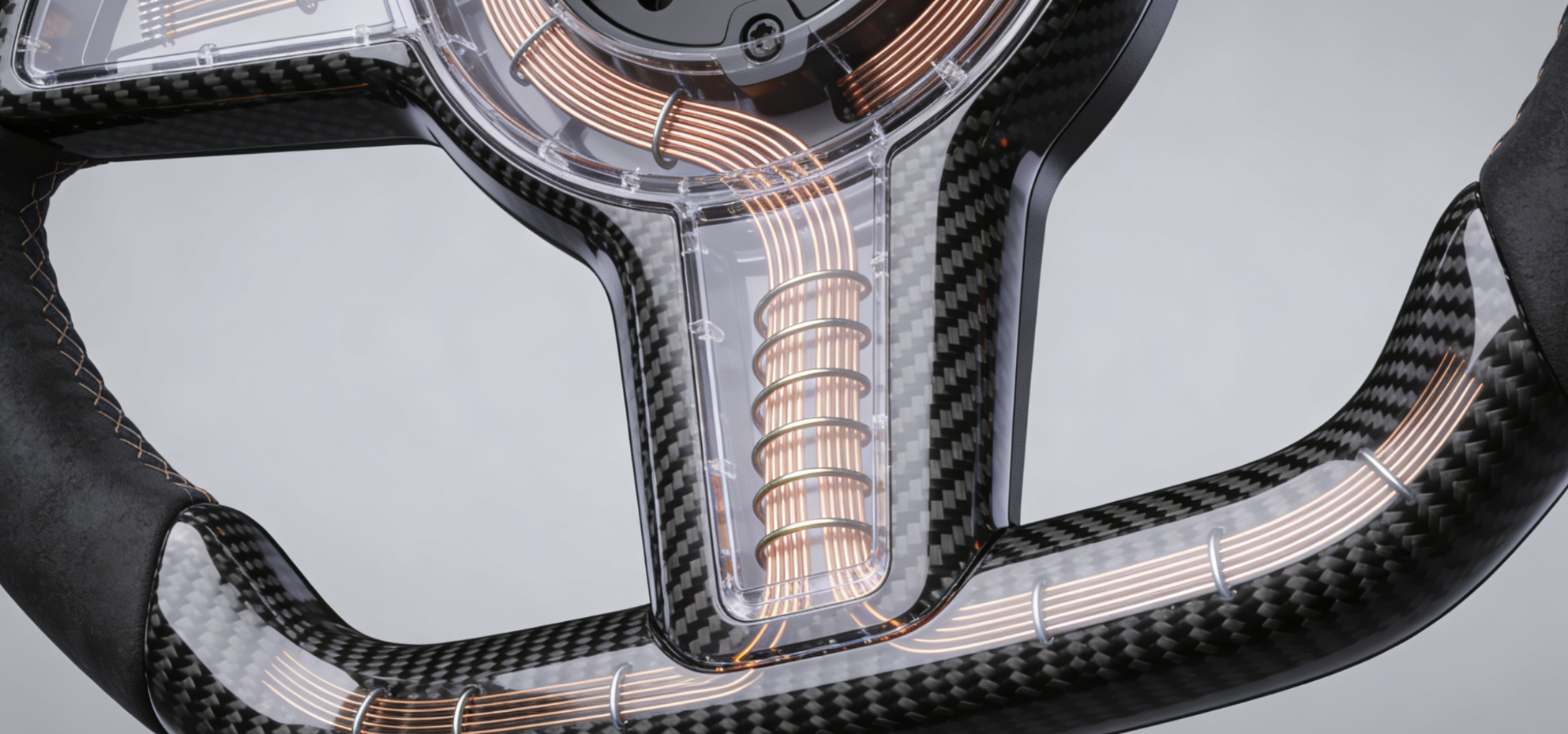
OEM heater-compatible models give you a real advantage — the harness infrastructure is already there. You’re not building a circuit from scratch. You’re adapting one built for this exact purpose.
Polarity is the critical variable. Get it wrong and you get no heat. Your BCM logs a DTC. A clockspring overload may trigger a warning lamp. The heater element runs on 54W at 12V — about 4.5A. That’s enough current to cause real damage flowing the wrong direction.
Confirm Polarity Before You Cut Anything
Switch your multimeter to continuity mode. Probe your OEM heater pins — on Toyota builds, that’s G175/H to z5/I. You want the W–B (White-Black) wire from the AG6 BAT feed connected to heater positive. The clean Black wire grounds to chassis. Then switch to resistance mode. A healthy element reads 680–700Ω total — about 350Ω per side. Infinite resistance means an open circuit. Stop there. Don’t wire anything until that reading is confirmed.
Solder or Crimp — Pick One and Do It Right
|
Method |
Resistance Impact |
Failure Risk |
|---|---|---|
|
Solder |
<0.1Ω per joint |
Low — vibration-proof |
|
Crimp |
+5–15% if loose (700→800Ω) |
10–20% higher under flex |
Crimping is faster. Soldering is more permanent. Both work with a clean execution. A loose crimp is a different story — resistance climbs past 800Ω, the element underperforms, and your system flags a fault regardless.
Routing and Anti-Pinch
Secure wiring to the clockspring output with zip ties every 100mm. Keep a 2–3cm strain relief loop at the connection point. The spiral cable needs a flex radius above 50mm. Clear airbag paths by at least 10mm — no exceptions on that. Run a full 900° lock-to-lock rotation test. Feel more than 5N of pull anywhere in that sweep? Fix the routing before closing anything up.
Post-install, scan for DTCs and watch the current draw. Anything above 5A points to a wiring fault — not a heater issue.
Common Mistakes & How to Avoid Them
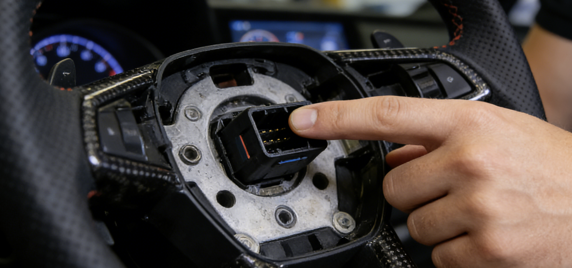
Most carbon fiber steering wheel installs don’t fail at the hard parts. They fail at the small ones — the steps that feel obvious until something goes wrong.
Here’s where people get it wrong, and what fixes it.
Skipping the static discharge step. Touch an airbag connector without grounding yourself first, and you leave no visible evidence of damage — until the airbag fails. Before touching any connector, press your hand against bare metal on the car’s frame. Do this every time. Not just the first touch.
Undertorquing the hub adapter. “Close enough” on torque specs gives you a wheel that vibrates at highway speed. The spec is 29 ft-lbs on the center bolt. Not 27. Not 31. Hit that number with a calibrated torque wrench. Don’t go by feel.
Pulling the clockspring cable tight to check for slack. It feels like a reasonable test. It isn’t. That ribbon cable has a fixed travel range. Stretch it once and it’s damaged — and the repair bill will cost more than the new wheel itself.
Reconnecting battery terminals in the wrong order. Positive first, then negative. Flip that sequence on a vehicle with active SRS systems, and you can trigger fault codes. Clearing those codes needs a dealer reset — not something you want to deal with after a straightforward install.
Seating connectors 90% of the way. A connector that clicks is seated. One that doesn’t click isn’t — no matter how solid it feels. Push until you hear it. Then stop.
The installs that go well aren’t the ones done fastest. They’re the ones done in order.
Conclusion
You’ve done the research. You’ve gathered the tools. You’ve walked through every step. Now it’s time to do it.
Here’s what matters most: disconnect that battery and respect the airbag system. Shortcuts there aren’t worth it. Get your hub adapter aligned right the first time. From there, the rest of the carbon fiber steering wheel installation falls into place. Running an RSI c6 or TESERY model? Take the extra 20 minutes for the OBD setup. It turns a cosmetic upgrade into a smarter driving experience.
This isn’t a job that needs a professional shop. It needs patience, the right tools, and following the sequence — in order.
Contact HyperX Carbon – Your Trusted Chinese Carbon Fiber Partner
Ready to source high-performance carbon fiber materials or custom forged carbon fiber parts from China?
HyperX Carbon is a leading manufacturer with 20+ years of expertise, specializing in aerospace-grade forged carbon fiber, prepreg, carbon fiber tube, carbon fiber sheet, and lightweight carbon fiber automotive parts/carbon fiber drone components/carbon fiber medical components. We offer:
-
Stable supply chain with premium raw materials (Toray, Mitsubishi, Hengshen)
-
AS9100D certified production for aerospace & UAV applications
-
Rapid prototyping (5-8 weeks) and monthly capacity exceeding 180,000 parts
-
Competitive pricing with 15-18% cost savings on forged carbon solutions
-
Full customization: from T700/T1100G to ultra-high modulus grades
Whether you’re an eVTOL developer, automotive OEM, drone manufacturer, or medical device engineer, HyperX delivers consistent quality, batch-to-batch reliability, and reliable delivery.
Get in touch today for a free consultation, custom quote, or material sample.
📧 Email: [email protected]
🌐 Website: https://www.hyperxcarbon.com/
📞 Phone/WhatsApp: +86 15623270276 (English support available)
Let’s build your next lightweight innovation together – contact HyperX Carbon now and stay ahead in the low-altitude and advanced composites market.