Choosing between standard carbon fiber products and custom parts is more than a purchasing call.
It is an engineering trade-off.
Your choice shapes performance, cost, lead time, tooling investment, maintenance cost, and production risk.
Get it right, and your application runs at peak efficiency. Get it wrong, and you are stuck overpaying for precision you do not need. Or worse, you are forcing an off-the-shelf part into a load case it was never built for.
This guide breaks down the real differences buyers need to evaluate:
- Cost structures — what you actually pay and why
- Lead times — how long each path takes
- Manufacturing implications — what each option demands from your process
- Performance ceilings — where each option hits its limits
- RFQ requirements — what a factory needs before giving a useful recommendation
From HyperX Carbon’s factory and engineering perspective, the question is not simply “standard or custom?” The real question is: which route gives the required performance with the lowest total project risk?
Quick Answer: Should You Choose Standard or Custom Carbon Fiber Parts?
Choosing between standard carbon fiber products and custom parts is more than a purchasing call.
It is an engineering trade-off.
Your choice shapes performance, cost, lead time, tooling investment, maintenance cost, and production risk.
Get it right, and your application runs at peak efficiency. Get it wrong, and you are stuck overpaying for precision you do not need. Or worse, you are forcing an off-the-shelf part into a load case it was never built for.
This guide breaks down the real differences buyers need to evaluate:
- Cost structures — what you actually pay and why
- Lead times — how long each path takes
- Manufacturing implications — what each option demands from your process
- Performance ceilings — where each option hits its limits
- RFQ requirements — what a factory needs before giving a useful recommendation
From HyperX Carbon’s factory and engineering perspective, the question is not simply “standard or custom?” The real question is: which route gives the required performance with the lowest total project risk?
Quick Comparison: Standard Carbon Fiber Products vs Custom Parts
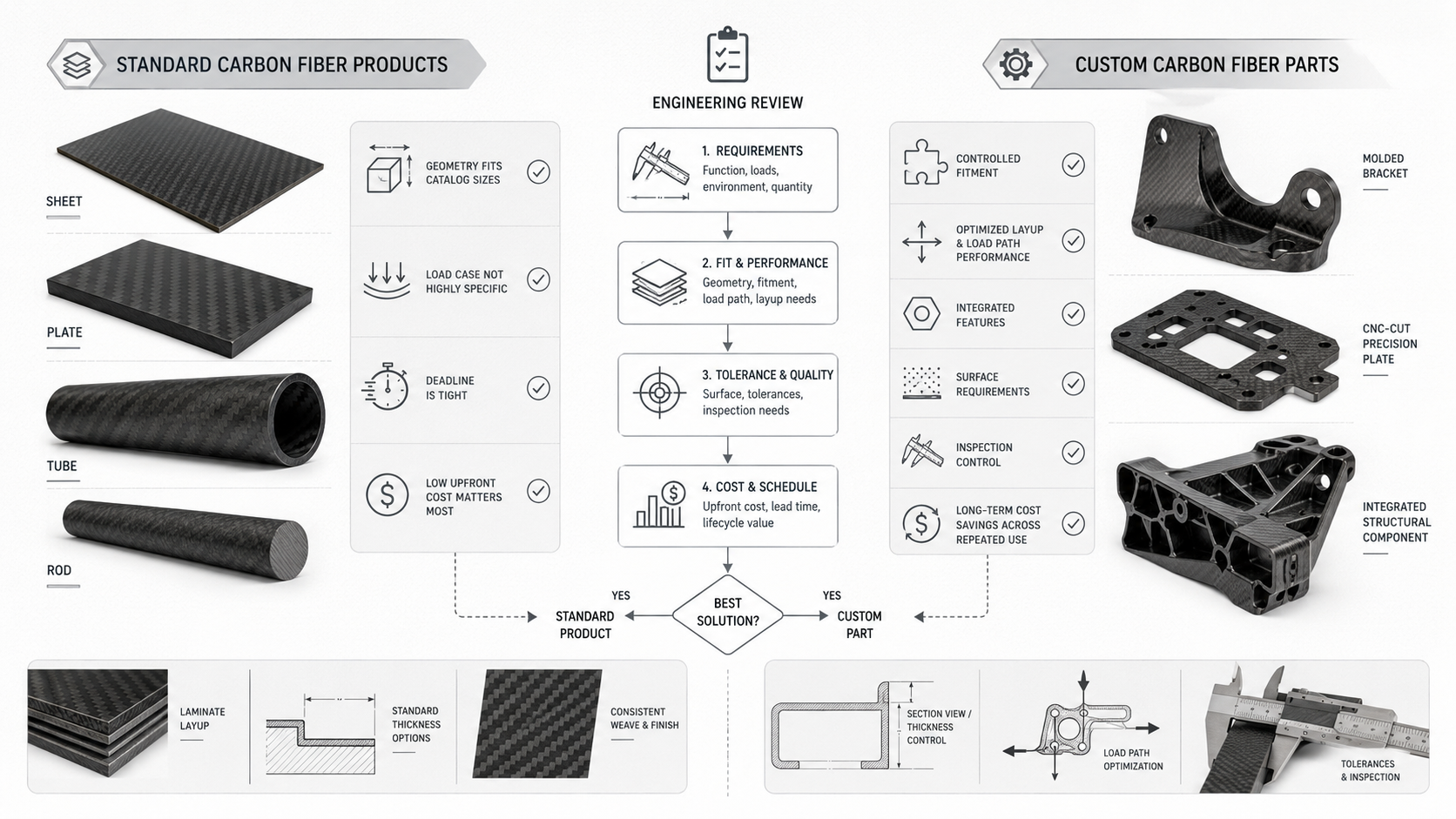
Two paths. One decision.
The numbers make it clear — if you know what to look for.
| Decision Factor | Standard Carbon Fiber | Custom Carbon Fiber |
|---|---|---|
| Unit Cost | ~$100 | ~$250, 2.5× higher |
| Lead Time | ~5 days | ~15 days |
| Tensile Strength | ~400 MPa | ~600 MPa |
| Weight vs. Steel | ~80% lighter | ~82% lighter, optimized |
| Long-Term Maintenance | Baseline | ~45% lower cost |
The upfront gap is real: $10,000 vs. $25,000 for a 100-unit batch.
But upfront price is not always the real project cost. Maintenance savings over the service life can close that gap in full.
Run through this five-question filter:
- Is the tensile strength requirement above 400 MPa?
- Is the weight reduction target above 50%?
- Would cutting maintenance costs by ~45% make a real difference to your budget?
- Can your schedule absorb 15 days instead of five?
- Does the application justify 2.5× the per-unit spend?
Three or more “yes” answers point toward custom.
Two or fewer usually mean standard stock components can get the job done.
At HyperX Carbon, we use this type of filter before discussing tooling or quotation. A custom part is not automatically better. A standard product is not automatically cheaper over the full lifecycle. The right answer depends on load, geometry, quantity, timeline, and maintenance risk.
What Are Standard Carbon Fiber Products?
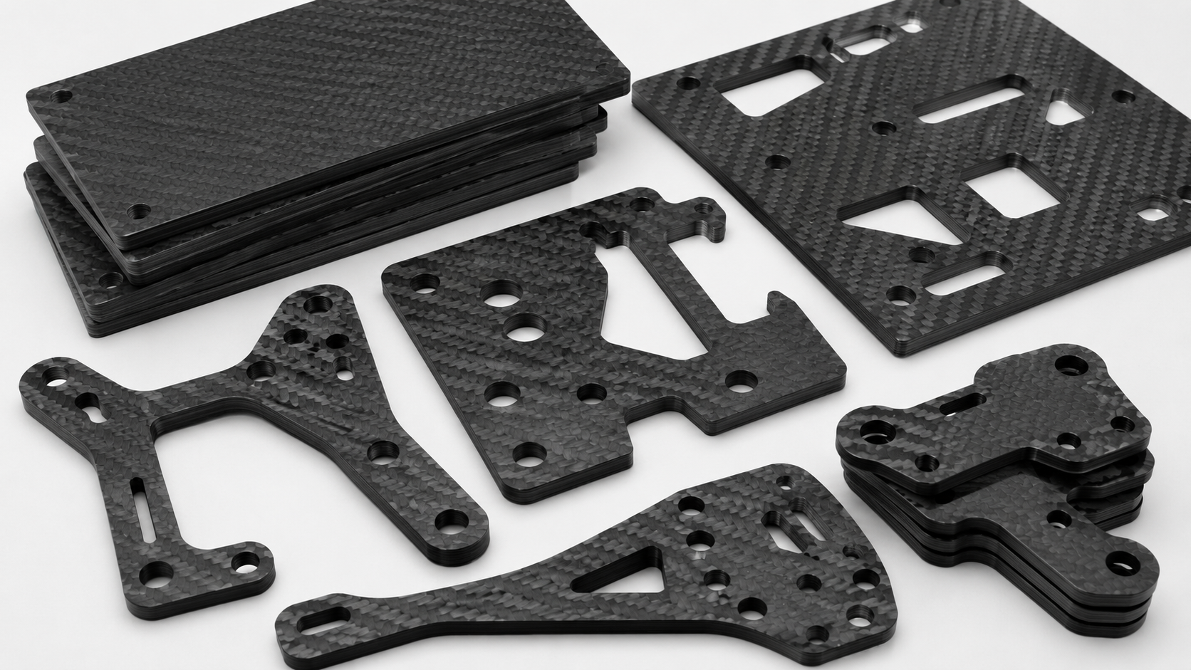
Standard carbon fiber products are stock components made to fixed, repeatable specifications.
They are ready to ship. No custom tooling. No design iteration. No waiting for mold development.
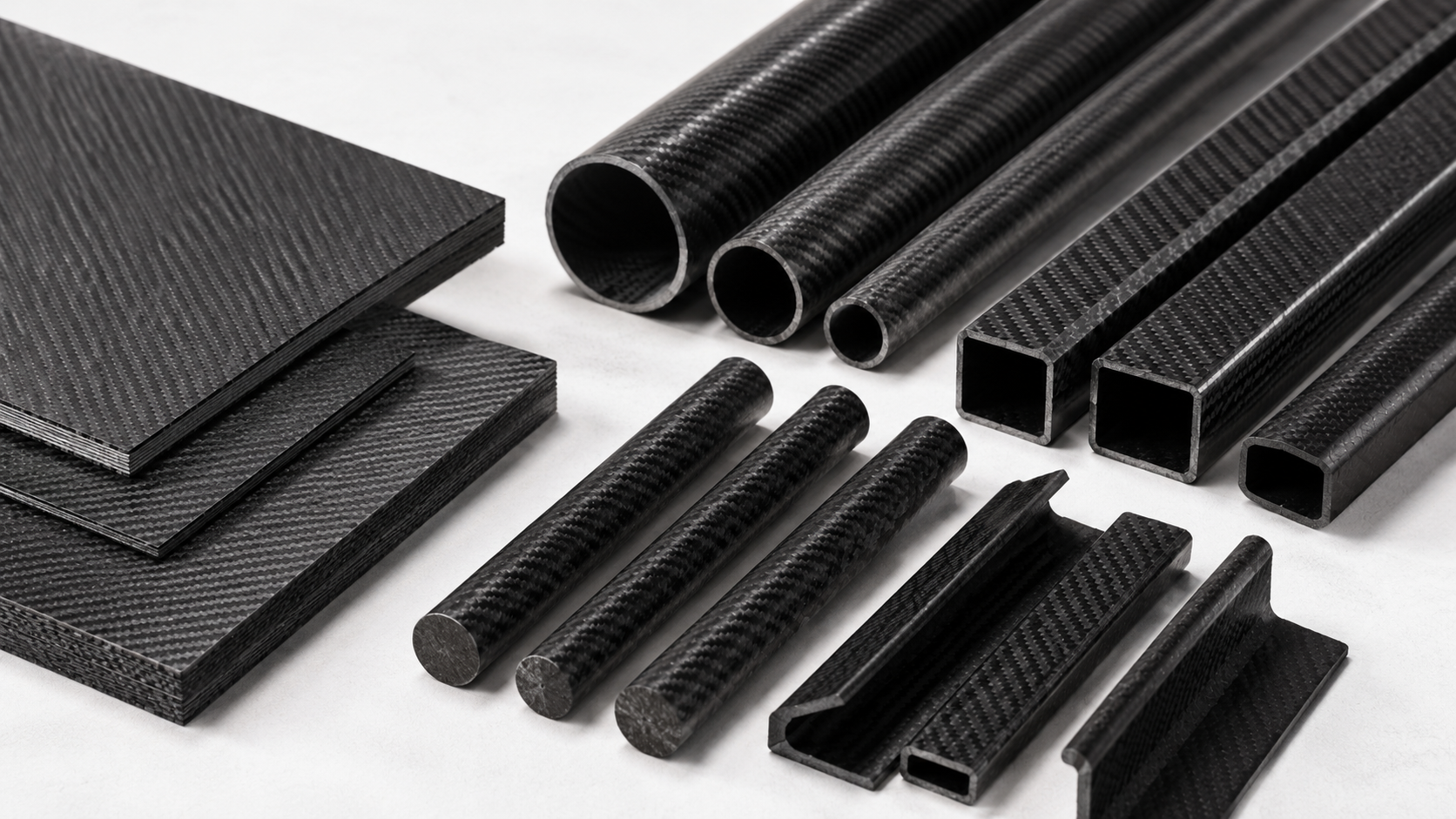
Standard carbon fiber products are usually structural semi-finished forms:
- Plates
- Sheets
- Tubes
- Rectangular bars
- Round rods
- Pultruded profiles
Manufacturers produce them through batch or serial processes using pre-defined geometry, fiber grade, and laminate architecture. Each batch can ship with documented mechanical property certificates, and every dimension falls within a published catalog range.
What Are Standard Carbon Fiber Products?
What “Standard” Means in Practice
Three parameters determine whether a carbon fiber component counts as a standard stock product.
1. Geometry Within Catalog Ranges
Standard parts begin with standard geometry.
Typical catalog ranges include:
- Flat plates / sheets: thickness from 0.5 mm to 10 mm, in standard increments such as 0.5, 1, 1.5, 2, 3, 4, 5, 8, and 10 mm
- Tubes: outer diameter 3–50 mm, wall thickness 0.5–3 mm, cut from continuous mandrel-wrapped stock lengths
- Rectangular bars and profiles: cross-sections matched to common metal hardware standards, such as 10×2 mm and 20×5 mm, sized for direct drop-in replacement
If your application can fit within these ranges, standard products can save time and avoid tooling cost.
If the geometry does not fit, the “standard” route usually becomes secondary cutting, drilling, shimming, grinding, or assembly compromise.
That is where many standard-part projects start losing the cost advantage they were supposed to protect.
2. Standard-Modulus Fiber
Stock components usually use standard-modulus PAN-based carbon fiber.
This gives a tensile modulus of 230–240 GPa and an ultimate tensile strength of 3.5 GPa, or 500 ksi.
This grade covers aerospace, automotive, industrial, and wind energy structural applications. It is the industry default for a reason: it gives a practical balance of strength, stiffness, availability, and cost.
For many applications, standard-modulus fiber is enough.
The real question is whether the stock geometry and stock layup match your load case.
3. Defined Layup Architecture
Standard stock plates follow a limited set of proven layup patterns:
- Quasi-isotropic [0°/90°/±45°] — balanced in-plane properties for general structural use
- Symmetric [0/90]s or [0/±45/90]s using plain weave or 2×2 twill woven fabric
- Tube layups using unidirectional axial plies for bending stiffness, plus ±45° or 90° hoop wraps for torsion resistance
Fabric formats follow set standards too:
- Plain weave
- 2×2 twill
- Unidirectional tape
- Areal weights in the 150–300 gsm range per ply
- Tow sizes of 3K, 6K, or 12K, meaning 3,000 to 12,000 filaments per bundle
Tow size controls ply thickness, and ply thickness helps set the standard plate thickness intervals seen across product catalogs.
Epoxy matrix is standard across these categories. Not because it is the cheapest — it is not — but because it delivers the best mix of strength, stiffness, and fatigue resistance among common resin systems for prepreg carbon fiber parts.
Standard Carbon Fiber Product Categories
Standard carbon fiber products can support many real applications when the geometry and load case are suitable.
| Category | Typical Spec Range | Common Applications |
| Stock CF plates | 0.5–10 mm thick, CFRP density ~1.5–1.6 g/cm³ | Structural skins, jigs, fixtures |
| CF tubes | OD 3–50 mm, wall 0.5–3 mm | UAV booms, robotic arms, sports shafts |
| Rectangular bars | Widths matched to metal standards | Linkages, frames, drop-in metal replacement |
| Pultruded profiles | I-beams, L-profiles, 1–5 mm wall | Industrial beams, stiffeners, bracing |
| Automotive stock parts | 1.5–2.0 mm skins, 2×2 twill surface | Trim panels, mirror housings, aero add-ons |
Standard CFRP stock hits an in-plane tensile modulus of 70–140 GPa, depending on layup and fiber volume fraction.
That gives weight reductions of 30–70% versus steel at comparable stiffness levels.
This is the performance floor.
Custom parts build above it.
For a broad range of structural applications, though, this floor is more than enough.
At HyperX Carbon, standard stock is usually a strong starting point when the buyer needs fast prototypes, simple brackets, flat panels, jigs, fixtures, standard tubes, or early-stage validation before committing to custom tooling.
What Are Custom Carbon Fiber Parts?
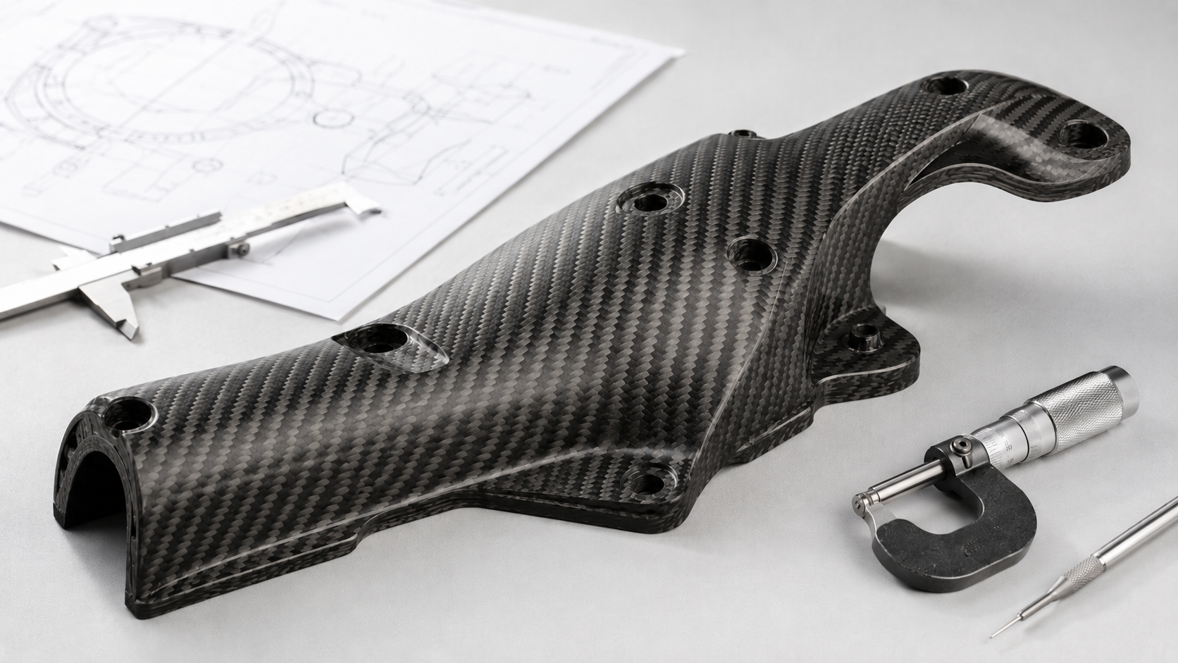
Every load path tells a story.
Custom carbon fiber parts are built to follow it.
Standard stock components use fixed geometry and generic quasi-isotropic layups. They serve the broadest possible market.
Custom carbon fiber parts start from the application. The fiber orientations, ply sequence, wall thickness, and overall geometry come from your CAD model and your load case.
Nothing is assumed. Nothing is borrowed from a catalog.
That distinction matters more than it sounds.
Engineering Fiber Orientation to Load Paths
A standard plate spreads its fiber angles across 0°, ±45°, and 90°. It has no idea what you will use it for.
A custom part does.
FEA-driven structural analysis sets the ply schedule. Each layer gets a specific angle and sequence. Together, they follow the actual stress vectors through the component.
The result: a custom laminate can deliver 2–4× higher stiffness along its primary load axis compared with a quasi-isotropic laminate of the same thickness.
That is not a small gain.
That is a different component.
Two laminate examples show the gap:
- High-stiffness beam: [0/0/±45/0/90]s — the majority of 0° plies carry axial load, ±45° handles shear, and 90° stabilizes transverse edges
- Quasi-isotropic housing panel: [0/±45/90]s repeated — balanced in-plane properties, often used as a starting baseline before load-specific optimization
The gap between these schedules is not only theoretical.
A generic layup can carry 20–40% extra mass that a well-optimized anisotropic laminate would cut out.
From a factory engineering perspective, that is why a custom carbon fiber part should not be defined only by outside shape. It needs a layup strategy.
What Custom Carbon Fiber Requires: The Ply Book
Every custom carbon fiber component should be defined by a ply book.
This is a documented engineering record that specifies:
- Ply number and stacking sequence
- Material type, such as UD tape, woven fabric, or core
- Ply thickness, typically 0.15–0.25 mm per prepreg ply
- Fiber orientation at each layer
- Local wall thickness targets, such as 2.0–4.0 mm for motorsport aero parts or 4.0–10.0 mm for structural aerospace frames
This document is what separates a custom part from a trimmed standard sheet.
A ply book is engineering data, not a shop note.
For buyers, this matters because it gives the supplier, the production team, and the quality team the same definition of the part. Without it, the quote may look custom, but the part may still behave like a generic laminate.
The Custom Development Workflow
From RFQ to first article, a custom carbon fiber component moves through five stages.
| Stage | What Happens | Typical Duration |
| Requirements & CAD review | Load inputs, stiffness targets, manufacturing route selection | 0.5–3 days |
| Structural design & layup definition | FEA optimization, ply angle assignment | 2–7 days |
| Tooling / mold fabrication | CNC-machined aluminum or composite tools, ±0.25–0.5 mm tolerance | 3–7 days |
| Layup & manufacture | Prepreg autoclave, 120–180°C, 3–7 bar; infusion; or hand layup | 1–5 days |
| Finishing, QC & delivery | CNC trimming, ultrasonic C-scan or thermographic NDT, OEM fitment check | 1–3 days |
Total first-article cycle: about 15–30 days for most motorsport and industrial projects.
Repeat production batches compress to 3–10 days per batch once tooling exists.
At HyperX Carbon, this is why we separate first-article timing from repeat-production timing. The first custom part pays for engineering, tooling, and validation. Repeat parts pay for controlled production.
Where Custom Carbon Fiber Parts Get Used
Custom carbon fiber components show up wherever standard geometry cannot solve the problem.
Common examples include:
- Motorsport: front splitters, rear wings, diffusers, and monocoque tubs. Prepreg UD or twill at 2–4 mm, with layups built to resist 1–3 kN downforce loads while adding minimal mass.
- Aerospace: fuselage skins, wing spars, and stiffened panels. Automated Fiber Placement, or AFP, machines lay 16 simultaneous prepreg strips at precise angles across complex surface geometries.
- Medical equipment: prosthetic components, imaging housings, and orthotic shells. CAD-driven geometries fit patient anatomy or OEM machine envelopes and can be 30–50% lighter than equivalent metal structures.
- Robotics and industrial automation: robot arms, end-effectors, and precision beams built to cut inertia and sharpen dynamic response along actuator force vectors.
All of these share the same need: the geometry is complex, the load case is specific, and an off-the-shelf tube or plate was never going to work.
Cost Comparison: Upfront Price vs Long-Term Value
The sticker price is almost never the real price.
Most buyers compare standard carbon fiber products against custom carbon fiber parts and stop at the purchase order.
The actual numbers keep adding up long after that.
Here is the baseline:
- Standard stock components: about $100 per piece
- Custom parts: about $250 per piece after tooling, engineering, and production are included
- Gap at 100 units: 2.5×
That is real money.
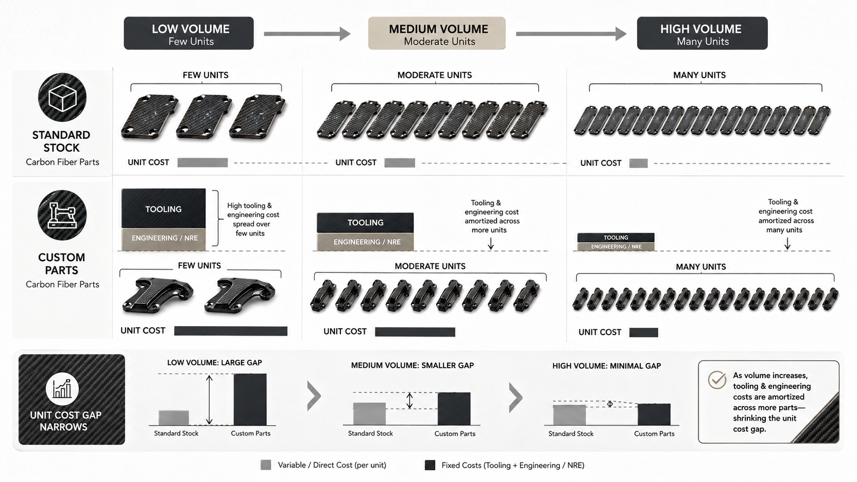
But the $250 figure carries a cost structure that shifts quickly with volume.
What You Are Paying For
At 100 units, the custom part breaks down like this:
- Tooling / mold: $10,000 one-time → allocates to $100/pc
- Engineering / NRE: $5,000 one-time → allocates to $50/pc
- Unit manufacturing cost: $100/pc
- Effective total: $250/pc
Scale the order and the math moves fast.
| Volume | Custom Unit Cost | vs. Standard, $100 |
| 100 pcs | $250/pc | +150% |
| 500 pcs | $130/pc | +30% |
| 1,000 pcs | $115/pc | +15% |
| 5,000 pcs | $103/pc | +3% |
| 10,000 pcs | $101.50/pc | +1.5% |
The $15,000 in fixed NRE and tooling is the main reason custom parts look more expensive at low volume. The manufacturing cost itself is identical in this model.
At 5,000+ units, the price gap is nearly gone.
This is why HyperX Carbon reviews quantity and lifecycle demand before recommending tooling. A custom part that looks expensive at 100 pieces can become economical at production volume.
The Lifecycle Math That Changes the Decision
Run a racing program scenario.
A standard suspension component costs $100. Under competition loads, a team replaces it 10 times per season. Add $80/hour labor at one hour per swap.
Standard parts season cost per car:
- $1,000 parts
- $800 labor
- Total: $1,800
A well-engineered custom carbon fiber component — with optimized layup and load-specific fiber orientation — cuts replacement frequency by 70%.
That means 3 swaps per season instead of 10.
Custom parts season cost per car:
- $750 parts
- $240 labor
- Total: $990
Across a 10-car fleet over three seasons, that gap compounds.
| Option | Total Maintenance | NRE | Total Program Cost |
| Standard | $54,000 | — | $54,000 |
| Custom | $29,700 | $15,000 | $44,700 |
| Net Saving | $9,300, about 17% |
The custom option costs more per piece.
It still wins by $9,300 across the full program.
That is the difference between unit cost and total cost of ownership.
Where the Hidden Costs Live
Direct maintenance is the obvious line item.
These costs rarely show up in the initial comparison — but they belong there:
- Scrap and defect rates: Design-optimized custom parts can cut scrap by 20–40%, reducing material waste and rework overhead across production runs.
- Energy efficiency: Custom-engineered systems can pull 10–30% less operational energy over the equipment’s service life.
- Residual value: Higher-quality structural components can hold 15–25% more value at end of life, which matters for leased equipment, fleet assets, or anything planned for resale.
From a procurement perspective, standard is usually better when the goal is fast, low-risk purchasing. Custom becomes stronger when the part affects maintenance, downtime, energy use, warranty, or repeat production.
Budget Stage Decision Guide
Not every project is a 10-car racing fleet.
The right call depends on where you are in the program.
Prototype / Small Batch: 10–100 Pieces
At this stage, NRE can make up 60–70% of the effective unit cost.
Go with standard stock unless the component is performance-critical.
Keep catalog parts at 70–80% of your prototype BOM.
For early validation, standard parts often help you move faster and avoid locking into tooling too early.
Medium Batch: 100–1,000 Pieces
Amortized NRE drops from $150/pc to $15/pc across this range.
Custom tooling makes sense when expected lifecycle savings per unit exceed $30–50 versus standard.
Payback on NRE should land within 2–3 years.
High Volume: 5,000+ Pieces
NRE allocation falls below $3/pc.
At this scale, the carbon fiber fabrication cost difference between custom and standard becomes too small to dominate the decision.
Lifecycle savings — maintenance, downtime, warranty, production stability — drive the decision.
The upfront price comparison is the starting point. Total cost of ownership is where the real decision lives.
Lead Time Comparison: Stock Speed vs Custom Development
Five days versus fifteen.
That is the typical gap — and it is not random.
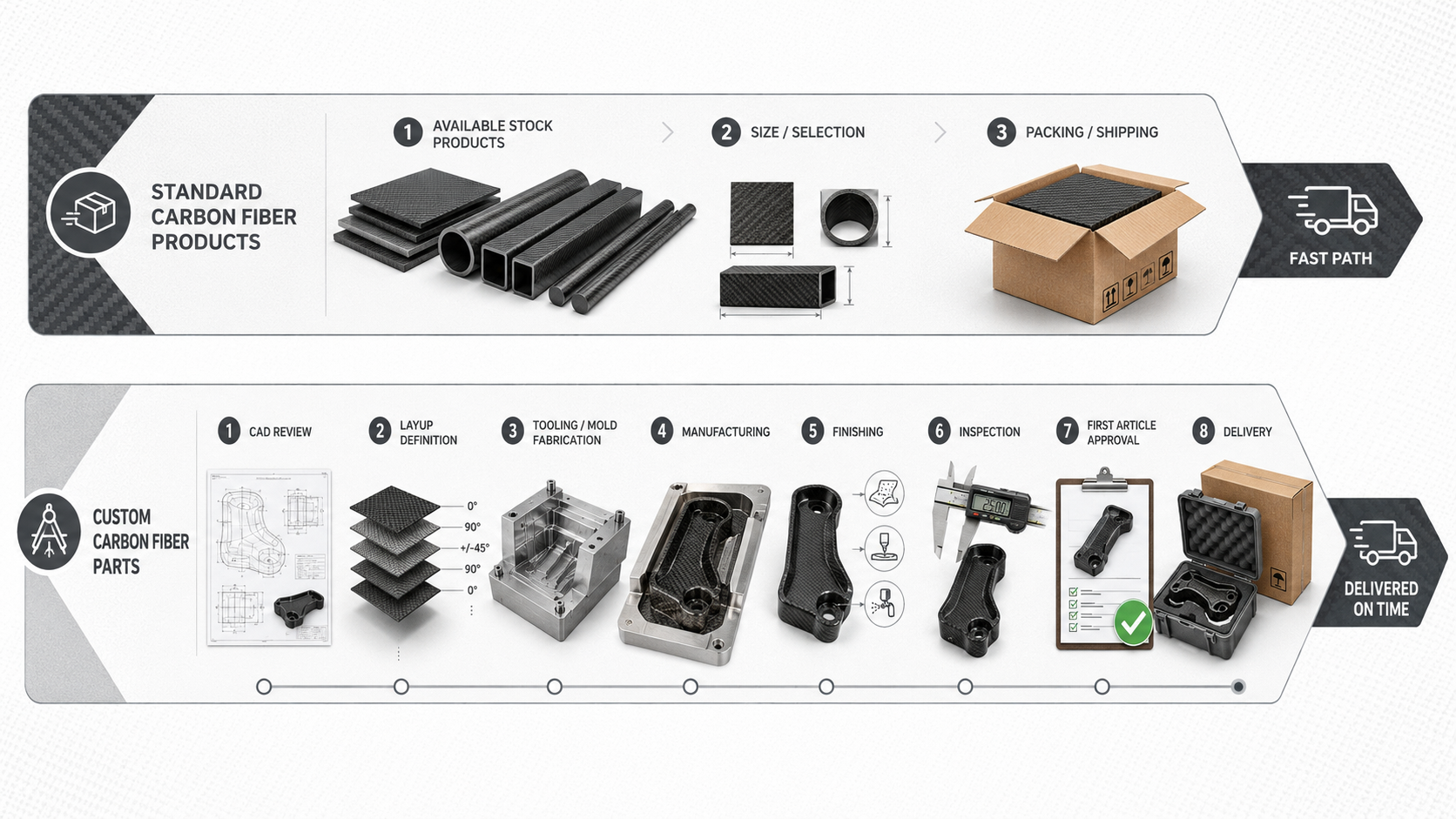
Standard carbon fiber products ship from existing stock. No tooling development. No engineering iteration. No mold trials.
Order before noon on a Tuesday, and parts can clear your receiving dock by the following week.
Custom carbon fiber parts require something stock components never do: they have to be built from scratch.
Mold design. Layup definition. First-article inspection. Each stage adds days before a single layer of prepreg touches a tool.
Lead Time Breakdown by Stage
| Phase | Standard CF Products | Custom CF Parts |
| Engineering & design | — | 2–7 days |
| Tooling / mold fabrication | — | 3–7 days, existing mold: 0 |
| Layup & manufacturing | Ready stock | 1–5 days |
| Finishing & QC | — | 1–3 days |
| Shipping, DHL / FedEx | 3–5 days | 3–5 days |
| Typical end-to-end | ~5–10 days | ~15–30 days, first article |
One number dominates the custom column: tooling.
An existing mold compresses the full timeline to 10–15 days.
No existing mold means 20–30 days minimum before first article delivery — and that is before any post-processing.
What Drives Custom Lead Times
Complexity does not grow at a steady rate.
It compounds.
Geometry is the first multiplier. A part you can machine in a single setup runs 3–5 days in production. Add deep cavities, thin walls, or multi-surface features. Now you may be scheduling 2–3× more operations, pushing production alone to 7–10 days.
Surface finishing is the factor many buyers underestimate.
A single anodizing or powder-coat step adds 7–10 days to any timeline. It routes through a third-party facility running on its own schedule.
Two finishing processes stacked?
Add 14–20 days — no matter how fast the machining went.
Materials matter too. Standard-spec carbon fiber — prepreg, epoxy system, standard-modulus PAN fiber — ships from local stock. Specialty resins or exotic fiber grades carry 5–15 day procurement delays.
Those delays push your total lead time back before manufacturing even starts.
At HyperX Carbon, we review material availability, mold status, finishing requirements, QC scope, and shipping method before giving a timeline. A realistic lead time is built from the full production route, not only from the molding step.
Need It Fast? The Rush Path
Some custom carbon fiber parts can move fast — just not all of them.
These are the conditions that make a fast-track timeline possible:
- Standard material grade
- No special procurement
- Geometry achievable in a single setup
- No complex surface finishing — sandblasting or clear coat only
- Quantity: 1–5 pieces
Hit all four, and expedited CNC prototyping services can compress production to 1–3 days.
Add 1–3 days for air freight.
A functional custom prototype can land in 4–6 days total — close to standard stock speed.
Add simple anodizing, and that same part lands in 7–10 days.
That is still 30–50% faster than the standard 15–20 day custom window.
Matching Timeline to the Right Option
The real question is not “which is faster?”
The real question is: which option is fast enough for where you are in the program?
Deadline Is ≤10 Days
Standard stock carbon fiber components are your path.
Use catalog geometry. Skip new tooling. Ship standard freight. Prototype with off-the-shelf plates or tubes, validate the load case, and save the custom development cycle for later.
You Have 15–30 Days
A custom part with one surface treatment and straightforward geometry is realistic.
Design for one-setup machining. Lock the surface finish requirement up front. The schedule can hold.
You Are Planning Production 8–12 Weeks Out
Start custom tooling development now.
Do not wait for production sign-off to begin mold design. Engineering teams that launch tooling at the DVT stage — not the PVT stage — are the ones who hit launch dates.
The 7–21 day mold window will not shrink just because launch pressure increases.
Repeat production changes the math. Once tooling exists, custom carbon fiber parts run in 3–10 days per batch — close to standard stock speed.
The lead time premium is a one-time development cost, not a permanent condition.
Performance Showdown: Strength-to-Weight, Stiffness, and Fitment

Carbon fiber’s strength-to-weight ratio is not marketing language.
It is physics.
Prepreg carbon fiber delivers 6–12× the tensile strength of steel at one-quarter the density.
That gives a specific strength advantage of 24–48× per unit of mass.
No structural material in common manufacturing comes close.
But the spec sheet does not tell the whole story.
How the material performs depends on what you do with the fibers.
Standard Layups: Capable, But Generalized
Stock carbon fiber components use symmetric, quasi-isotropic layups — [0/90]s or [0/±45/90]s.
These schedules are built for versatility. They handle load from multiple directions.
That is also the limitation.
Adequate is not the same as optimal.
A quasi-isotropic laminate has no opinion about your load case. It spreads fiber angles across all directions in equal measure.
Under axial tension testing, a pure carbon laminate hits ultimate loads around 8,630 N.
A carbon/glass hybrid with a similar cross-section lands at 4,850 N — a 44% gap driven by fiber system and layup choices, not geometry.
The same logic runs in reverse in real applications. Stress concentrations appear along short edges. Mid-span loads stay low. A misaligned load path and fiber orientation is a setup for interlaminar shear failure.
That is not a theoretical risk.
It is a real one.
The result: designers using standard parts add thickness to cover the worst-case direction. That adds 10–30% excess mass compared with what a purpose-built laminate needs.
Or they hold wall thickness and accept 80–90% of the required safety margin on the critical axis.
Either way, something is lost — weight, structural life, or safety margin.
Custom Layups: Stiffness Where It Counts
A custom carbon fiber part starts with FEA.
You map the stress vectors through the component. Then you assign fiber angles to follow them.
A high-stiffness beam schedule — [0/0/±45/0/90]s — loads most 0° plies onto the primary tensile axis. The ±45° layers take shear. The 90° plies stabilize transverse edges.
Nothing goes to waste.
Stack that against a generic quasi-isotropic laminate of the same thickness, and the purpose-built layup gives 2–4× higher stiffness along its primary load axis.
Load-path-optimized custom laminates deliver about 15% stiffness and strength improvement over equivalent-weight quasi-isotropic designs.
That 15% is grounded in laminate test data — the same fiber-system optimization that pushes tensile capacity from 4,850 N up to 8,630 N.
On a racing platform, that 15% structural stiffness gain feeds straight into lap time. You get tighter suspension connection-point stiffness, more linear braking response, and a more consistent tire contact patch.
The documented result: 1.5–3.0 seconds per lap gained on high-performance vehicles that switched from generic carbon components to directional-layup custom parts.
Fitment: The Performance Variable Nobody Budgets For
A standard carbon fiber tube does not know what chassis it is going into.
The installer does — and that is where the rework starts.
Cutting, drilling, slotting, and grinding are standard steps when catalog parts are forced into real geometry. Each one severs fibers. Each severed fiber becomes a stress concentrator.
Engineers then add larger safety factors or local reinforcement patches to compensate.
That adds back the weight the material switch was supposed to eliminate.
The numbers are clear:
- Field-modified standard parts: ±0.5–1.0 mm positional error at critical mounting holes after secondary machining
- Custom carbon fiber components machined from CAD: ≤±0.1 mm at installation surfaces and critical hole locations
That is 50–80% tighter.
On a double-wishbone suspension, a ±0.5 mm error in a carbon linkage introduces 0.1–0.3° of camber or toe deviation based on geometry.
For a high-grip tire compound, 0.2° of camber error alone costs 0.1–0.3 seconds per lap through degraded contact patch loading.
Stack that across multiple structural nodes and the cumulative loss can reach 0.5–1.0 s/lap.
Custom carbon fiber components with ≤±0.1 mm interface accuracy can keep geometry error at ≤0.1°, with lap-time influence below 0.1 s/lap.
From HyperX Carbon’s manufacturing perspective, this is why fitment is not a secondary detail. Fitment controls whether the theoretical strength-to-weight advantage becomes real system performance.
The Combined Performance Picture
Three effects stack together.
| Performance Variable | Standard CF Part | Custom CF Part | Delta |
| Specific strength vs. steel | 24–48× baseline | 24–48× + layup optimization | ≈+15% on primary axis |
| Stiffness, primary load axis | Quasi-isotropic baseline | FEA-optimized layup | +15–40% |
| Fitment tolerance, mounting holes | ±0.5–1.0 mm | ≤±0.1 mm | 50–80% tighter |
| Geometry error, suspension | 0.1–0.3° | ≤0.1° | — |
| Combined lap time impact | Baseline | ≈−2.0 s/lap | measurable, documented |
The ≈2 second per lap figure is not a single-variable claim. It is the combined result of directional stiffness gains plus precision fitment reducing cumulative geometry error.
The same physical logic — strength-to-weight and stiffness-to-weight optimization converting into system efficiency — appears in wind turbine blade engineering too, where carbon fiber substitution produces 20–30% weight reduction and a measurable increase in annual energy yield.
The principle holds across every application:
Material properties set the ceiling. Layup direction and dimensional accuracy determine how close you get to it.
Scenario-Based Decision Guide: Standard vs. Custom Carbon Fiber
Three variables decide almost every carbon fiber procurement question:
- Load criticality
- Annual volume
- Geometric fit
Nail those three, and the standard-versus-custom debate becomes much clearer.
Go With Standard Carbon Fiber Products When
Load Requirements Are Low and Geometry Is Flexible
Your safety factor sits at ≤1.5. Failure does not risk personnel or core equipment.
Standard stock handles the job.
Decorative panels, lightweight brackets under 500 N, and cosmetic trim do not justify tooling investment.
Your Timeline Is Under 10 Days
Design freeze to SOP in less than 8–12 weeks?
Custom tooling will not make it.
Standard catalog parts ship from stock. That is the one path that can hit the deadline.
Geometry Already Fits Catalog Specs
If 80% or more of your part’s features match standard dimensions — M-series bolt holes, plate thicknesses such as 0.8, 1.0, 1.5, or 2.0 mm, or common tube ODs — a few shims or spacers may close the gap.
No new mold needed.
Standard products are strongest when speed, cost control, and acceptable geometry matter more than maximum optimization.
Go With Custom Carbon Fiber Parts When
Performance Is Non-Negotiable
Safety factors of ≥2.0–3.0, fatigue life targets above 10⁶ cycles, and weight reduction goals of 10–30% usually go beyond what a quasi-isotropic stock laminate can deliver with consistency.
The Space Is Constrained
A part needs to route around obstacles, connect to multiple mounting points, and carry structural load all at once.
Standard profiles cannot do that.
Geometry that deviates more than 20–30% from any catalog profile needs a custom solution.
Volume Makes Tooling Cost Worth It
Target around 30,000–50,000 pieces over three years.
At that volume, a $10,000–$25,000 mold amortizes below $1 per unit.
The economics shift fast at that point.
Custom parts are strongest when performance, geometry, lifecycle cost, or production repeatability matters more than first-piece price.
Try a Hybrid Strategy When Neither Option Fits
Many real projects do not fit cleanly into “all standard” or “all custom.”
Use standard plate and tube for 70–80% of the structure.
Add custom-fabricated connection nodes and load-bearing interfaces for the remaining 20–30%.
That split gives catalog speed and cost on most of the BOM. You place high-performance carbon fiber components exactly where the structure needs them most.
The result: 25–40% lower total cost of ownership compared with going all-custom, without the performance trade-offs that come with going all-standard.
At HyperX Carbon, this hybrid strategy is often the most practical route for prototypes, robotics frames, UAV structures, motorsport brackets, and industrial assemblies where only certain zones carry critical load.
Key Decision Checklist: 6 Factors Before You Place an Order
Six questions separate a smart procurement decision from an expensive mistake.
Work through each factor below. By the end, the right path — standard stock carbon fiber components, custom-built parts, or a hybrid route — should be clearer.
Factor 1: Load Level and Safety Criticality
Does your part absorb dynamic impact loads above 3g acceleration at cycle frequencies over 10 Hz?
Does failure mean a medical device stops working, a race car loses structural integrity, or a production line goes dark at a cost above $100,000?
If yes, you need custom carbon fiber parts.
That means:
- Static safety factor of SF ≥ 2.0
- Third-party tensile and fatigue test reports
- ISO 9001 compliance documentation available on request
If no, standard stock components with SF ≥ 1.5 may cover the load case.
Before placing any order on a safety-critical part, confirm:
- Third-party test reports, including tensile, fatigue, or impact
- Warranty terms — 12–24 months is standard for structural components
- Failure liability written into the contract, not assumed
Safety-critical parts need documented engineering support, not only material claims.
Factor 2: Strength-to-Weight Requirement vs. Budget Reality
Two numbers tell the story:
- Target weight reduction
- Unit cost ceiling
Targeting ≥15% weight reduction over your current solution?
That is the point where carbon fiber fabrication — with a load-optimized layup — starts outperforming aluminum.
Below that threshold, 6061-T6 aluminum at about $40/kg gives 240 MPa yield strength and a density of 2.7 g/cm³.
It is capable. It is cheaper too.
Above that threshold, the carbon fiber strength-to-weight ratio — about 400–600 MPa tensile strength at 1.5–1.6 g/cm³ — does what aluminum cannot.
On the cost side, many buyers make one common mistake: comparing unit prices instead of total cost of ownership.
In B2B procurement, paying 10–30% more per unit can be justified when TCO drops by 15–20% through fewer maintenance cycles, lower replacement frequency, and less downtime.
Before committing to a budget number, verify that the quote includes:
- Unit cost
- Tooling amortization
- Freight
- Duties
- One-off pricing vs. long-term framework pricing
- TCO modeling across the part’s full service life
Factor 3: Geometry Complexity and Assembly Interface Requirements
Pull up your CAD model.
Count the features.
More than 10 precision mating surfaces?
Wall thickness under 2 mm?
Multi-axis compound curves?
Any of those push you toward custom carbon fiber manufacturing.
Standard plates and tubes cannot always be trimmed and drilled into those geometries without cutting load-bearing fibers and adding dimensional error.
Critical assembly interfaces with tolerances of ≤±0.01 mm are not catalog items.
That is a DFM conversation with your OEM carbon fiber components supplier before the first layer of prepreg gets laid.
Mixed interface standards — ISO tolerances combined with ASME threads and surface roughness Ra < 0.8 μm — add more risk.
Each unmapped combination is a rework event waiting to happen.
Pre-order geometry check:
- All datums, fit tolerances, GD&T callouts, and surface finishes marked in CAD
- No blank zones for the factory to interpret
- First Article Inspection, or FAI, required before batch release
- Supplier DFM / DFS review confirmed for any part with more than 20 geometric features
A factory cannot protect fitment accuracy if the drawing leaves key interfaces undefined.
Factor 4: Lead Time Tolerance
One question cuts through the schedule debate:
What does a one-week delay cost you?
A production line stoppage or contract penalty above 5% of order value changes the sourcing logic.
Your supplier selection needs to put delivery consistency ahead of unit price. Build buffer stock. Qualify a second source. Write expedite clauses into the PO.
If your program can absorb ±20% schedule variance, more suppliers become viable and you gain pricing leverage.
Check the timeline against your project gate:
| Option | In Stock | No Stock / First Article |
| Standard CF products | 3–7 days | 2–4 weeks |
| Custom CF parts | N/A | 3–6 weeks, tooling adds 4–8 weeks if new |
Before order placement, get written confirmation of:
- Typical lead time
- Worst-case lead time
- Expedite capability
- Remedies for late delivery, such as air freight coverage, price adjustment, or backup supplier access
Factor 5: Annual Volume and Tooling Amortization
The tooling math is unforgiving at low volumes.
A standard carbon fiber tooling and molds investment runs $5,000–$25,000, depending on geometry and surface complexity.
At 10,000 pieces over three years, that spreads to under $1 per unit.
At 1,000 pieces, the same mold adds $1.70–$8.30 per unit.
At 300 pieces, tooling may cost more than the parts themselves.
The volume thresholds that shift the decision:
- <500 units/year: standard stock or CNC-machined custom geometry. No mold investment.
- 500–5,000 units/year: run base, optimistic, and pessimistic scenarios. Model payback period against a 3–5 year amortization window.
- >5,000–10,000 units/year: tooling investment is justified. Custom carbon fiber fabrication cost per unit drops close to standard stock pricing at this scale.
Volume decision checklist:
- Annual demand forecast modeled across all three scenarios
- Tooling amortization period matches the product’s commercial lifespan
- For low volume, check whether CNC machining from standard plate is cheaper before ruling out standard catalog parts
Factor 6: Design and FEA Support Requirements
Not every engineering team has a structural analyst on staff.
That is not a weakness.
It is a procurement variable.
No in-house FEA capability?
Part is safety-critical, load-bearing, or made from a material your team has not specified before?
Then the supplier’s carbon fiber manufacturing process expertise needs to go beyond production.
You need:
- Topology optimization
- Linear static FEA
- Fatigue analysis
- Test correlation
- Documented engineering outputs, not verbal assurances
A basic FEA engagement runs $500–$2,000 per part with a 1–2 week turnaround.
Complex multi-load-case analysis stretches to 3–6 weeks.
Nail down both figures in your RFQ before the project starts — not after the first article comes back wrong.
Include in your RFQ:
- Simulation type required, such as static, fatigue, or thermal
- Verification standards and acceptance criteria
- Deliverable format: report, FEA file, or test correlation data
- Whether design / FEA fees are bundled into unit price or billed as separate NRE
At HyperX Carbon, this is one of the first points we clarify for custom projects. If the part requires engineering validation, that work needs to be scoped before quotation, not discovered after production starts.
Read the Pattern, Not the Number
Do not just add up points.
Read the pattern.
Multiple “yes” answers in Factors 1, 3, and 6 — load criticality, complex geometry, and no internal FEA — point clearly toward custom carbon fiber parts with full engineering support from the supplier.
Multiple “yes” answers in Factors 4 and 5 — tight timelines and low annual volume — pull toward standard carbon fiber products from catalog stock.
A mixed pattern across all six factors is the most common outcome.
That is where the hybrid strategy earns its keep: standard stock for 70–80% of the BOM, custom fabrication in the specific zones where the load case or geometry requires it.
The checklist does not make the decision for you.
It makes sure you have the right information before you do.
FAQ: Standard vs. Custom Carbon Fiber
Are Custom Carbon Fiber Parts Cheaper Over Time?
Upfront, no.
Standard parts run around $100/unit. Custom parts land around $250/unit.
That gap is real.
But run the five-year math.
A standard part with $1,000 in maintenance costs $1,100 total.
A load-optimized custom part in the same position cuts replacement frequency by ~45%.
Total cost drops to $800.
That is a 27% total cost reduction despite the higher purchase price.
Break-even lands around 20–40 pieces.
That is the point where lifecycle savings cover tooling and NRE costs.
How Long Does Custom Development Take?
CAD submission to first article takes about 15 days for simple parts.
Complex curved assemblies can take 30–45 days.
Typical breakdown:
- Requirements review: 1–3 days
- Layup design and FEA: 3–7 days
- Tooling: 7–10 days
- First-article production and QC: 3–5 days
What Is the Minimum Order for Custom Parts?
Simple CNC-cut custom plates may start at 5–10 pieces.
Molded 3D geometry usually needs 20–50 pieces to justify dedicated tooling.
A $4,000 mold spread over 20 units adds $200/pc.
Spread over 50 units, it drops to $80/pc.
MOQ exists for one reason: math.
Do Suppliers Provide FEA and Layup Design Support?
Many do.
Most bundle it into high-value projects or large MOQs.
Standalone FEA runs $500–$2,000 per part.
Submit your load cases, mounting conditions, and deflection limits.
A capable supplier should return a documented laminate schedule and validated simulation output.
For custom carbon fiber parts, engineering support should be documented, not assumed.
What Files Do You Need to Submit for a Custom Quote?
You need three things:
- A STEP or IGES file with final geometry
- A 2D drawing with tolerances and hole positions
- A technical brief covering fiber grade, resin type, load case, and annual volume
The quote comes back with tooling cost, usually $2,000–$10,000, per-unit pricing, and lead time.
Missing information means an incomplete quote.
Send complete files to get complete numbers.
Can I Buy Just One or Two Standard Carbon Fiber Parts?
Yes.
Standard sheets, tubes, and profiles often carry an MOQ of one piece.
Volume price breaks usually start at 10, 50, and 100 units.
For prototyping or spot replacement, single-unit purchasing from stock is normal.
It is also the standard path before volumes make custom tooling worth it.
Conclusion
Choosing between standard carbon fiber products and custom parts is not about which option is better.
It is about which one fits your application, timeline, load case, volume, and budget.
If your geometry is standard and speed matters, stock components get you moving fast.
If you need precise fitment, optimized layup, validated strength-to-weight performance, or a structure that off-the-shelf parts cannot match, custom is the right answer.
Do not let tooling costs or lead time assumptions steer you away from the correct route.
Ask the engineering question first:
Does this part need catalog speed, custom performance, or a hybrid structure?
At HyperX Carbon, we have built both standard carbon fiber products and custom carbon fiber parts. We know where the line is. We also know that the best decision is often not the most expensive one — it is the one that reduces project risk.
Send us your CAD file, 2D drawing, load case, target weight, tolerance requirement, surface requirement, quantity, and timeline.
Our engineering team can help review whether your project should start with standard stock, CNC-machined stock, a hybrid structure, or fully custom carbon fiber parts.
The right carbon fiber route should protect performance, budget, timeline, and production repeatability — not just satisfy a material specification.