Choosing the wrong carbon fiber product form wastes money — and it can silently damage an entire structure before any failure shows up.
You might not see it coming until it is too late.
A rod where a tube belongs. A sheet where fiber orientation was never planned. A pultruded tube used in torsion. A flat laminate asked to carry out-of-plane bending without enough stiffness.
These mismatches happen all the time, even with experienced designers.
The reason is simple: carbon fiber is anisotropic. Gut instinct from metal design does not work reliably.
Metals behave the same in every direction. Carbon fiber does not. Its performance shifts based on how the load travels through it, how the fibers are oriented, and which product form is chosen to carry that load.
That difference matters more than most buyers expect.
This guide removes the guesswork. By the end, you will know how to:
- Read a load case clearly
- Match it to the right carbon fiber product form
- Avoid rod, tube, sheet, and panel selection mistakes
- Build a product specification that a factory engineer can actually review
At HyperX Carbon, we do not start product-form selection by asking only whether the buyer wants a rod, tube, sheet, or panel. We start by asking: where does the load enter, where does it exit, and which fiber direction is supposed to carry it?
Quick Answer: Match the Carbon Fiber Product Form to the Dominant Load Case
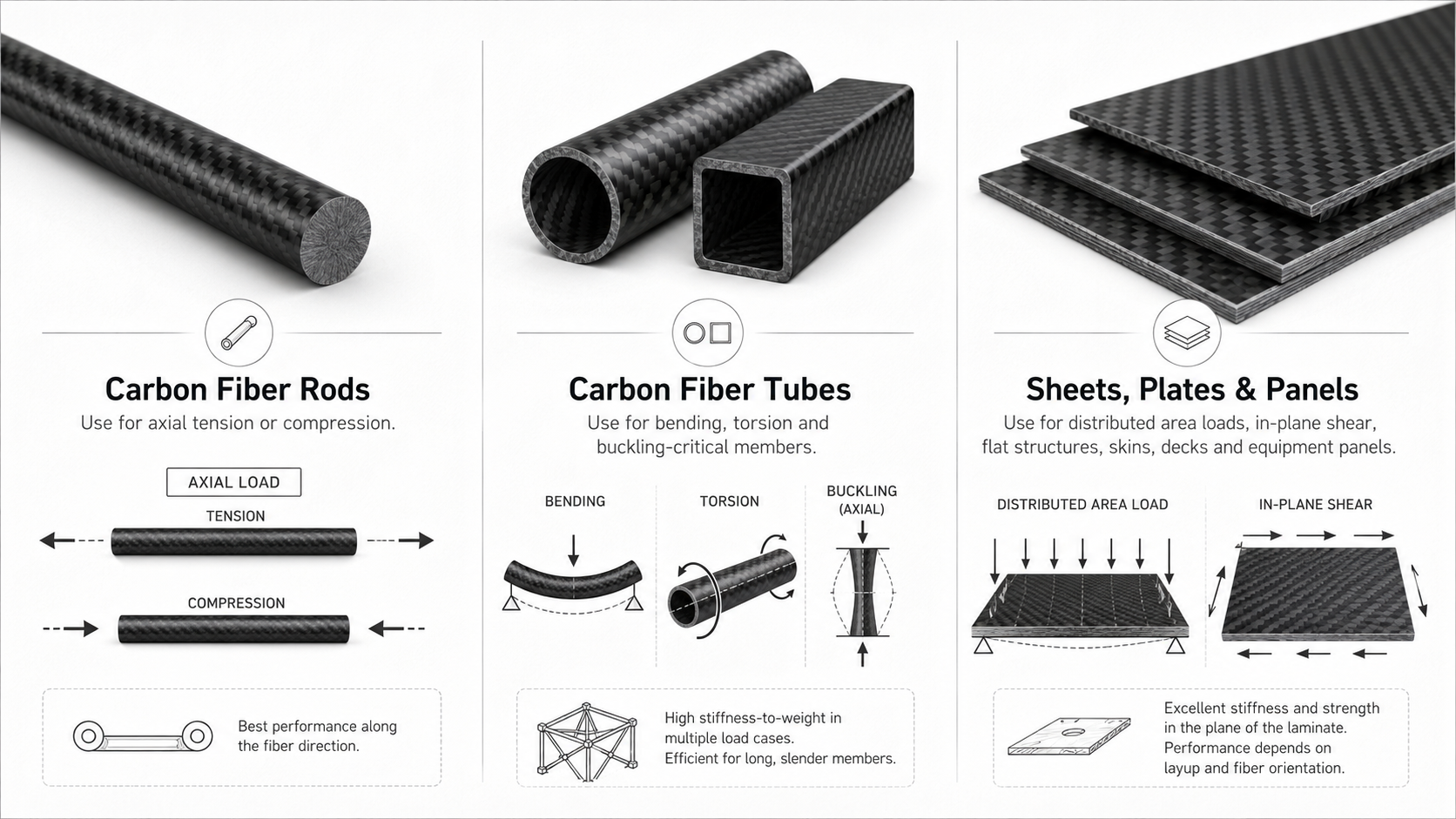
The fastest way to choose a carbon fiber form is to identify the dominant load case first.
Carbon fiber product forms are not interchangeable. Each form is strong for a different reason.
- Use rods when the load is clean axial tension or compression.
- Use tubes when bending, torsion, or buckling efficiency matters.
- Use sheets and panels when load is spread across an area or shear must be carried through a flat structure.
- Use sandwich panels when out-of-plane stiffness matters more than solid laminate thickness.
- Use custom layup when the load path is specific and standard fiber orientation does not match it.
Three decisions drive every successful carbon fiber selection:
- Where the load travels
- How the load is oriented
- Which form and fiber orientation can carry it efficiently
The basic matching logic is:
| Dominant Load Case | Usually Best Starting Form | Main Reason |
|---|---|---|
| Pure axial tension / compression | Pultruded rod or UD flat bar | Fibers run along the load path |
| Bending + torsion | Roll-wrapped round tube | Hollow geometry plus 0° and ±45° fibers |
| Buckling-critical compression | Hollow tube or box section | Higher section efficiency per gram |
| Distributed pressure | Sandwich panel | Core thickness increases bending stiffness efficiently |
| In-plane multiaxial panel load | Quasi-isotropic sheet / panel | Balanced stiffness across multiple directions |
| Shear-dominant web or torsion skin | ±45° dominant sheet / web | ±45° fibers carry shear efficiently |
The product form should follow the dominant load case. The layup should follow the dominant stress direction.
That is the core rule.
What Are Carbon Fiber Product Forms — And Why the Match Matters
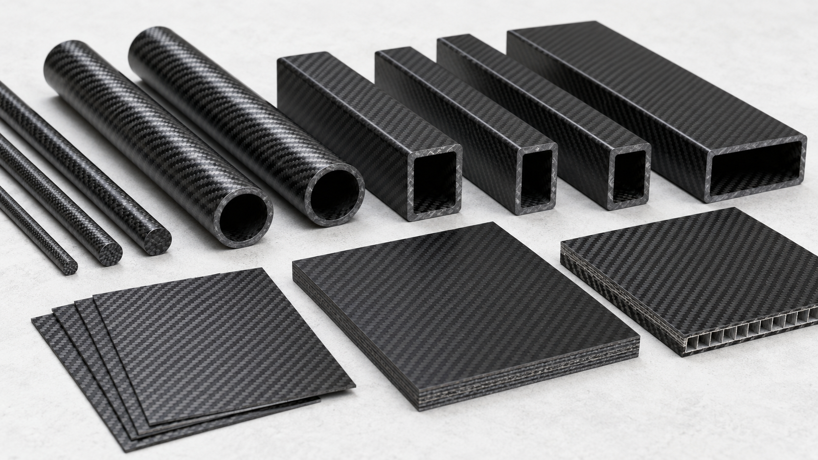
Carbon fiber comes in several physical product forms, including tubes, rods, sheets, panels, and custom laminates.
Each one is a different structural tool.
Choosing the wrong form for your application is not just a performance issue. It can cause outright failure.
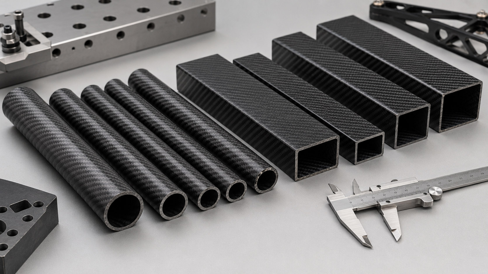
Carbon Fiber Tubes
Tubes are hollow cylindrical, square, or rectangular sections with thin walls.
The manufacturing method determines how the fibers are oriented, and that changes how the tube behaves:
- Pultruded tubes run almost all fibers at 0°, along the length. This maximizes axial and bending stiffness, but gives limited torsional capability.
- Roll-wrapped tubes stack plies at 0°, ±45°, and 90°. This balances bending, torsion, and crush resistance.
- Filament-wound tubes vary by winding angle, giving designers control over specific load directions.
Same outer shape.
Very different behavior under load.
From a factory perspective, this is why OD and wall thickness are not enough for a tube recommendation. HyperX Carbon also needs to know torsion, bending, clamp zones, joint design, and whether the tube is pultruded, roll-wrapped, or filament-wound.
Carbon Fiber Rods
Rods are solid and usually pultruded.
Fibers run along the length. That gives rods exceptional longitudinal tensile strength — anywhere from 1,000 to 3,500 MPa.
But lateral and torsional capacity are minimal.
That is by design, not a flaw.
A carbon fiber rod is an axial-load tool. It is not a universal lightweight replacement for every metal bar.
Carbon Fiber Sheets and Panels
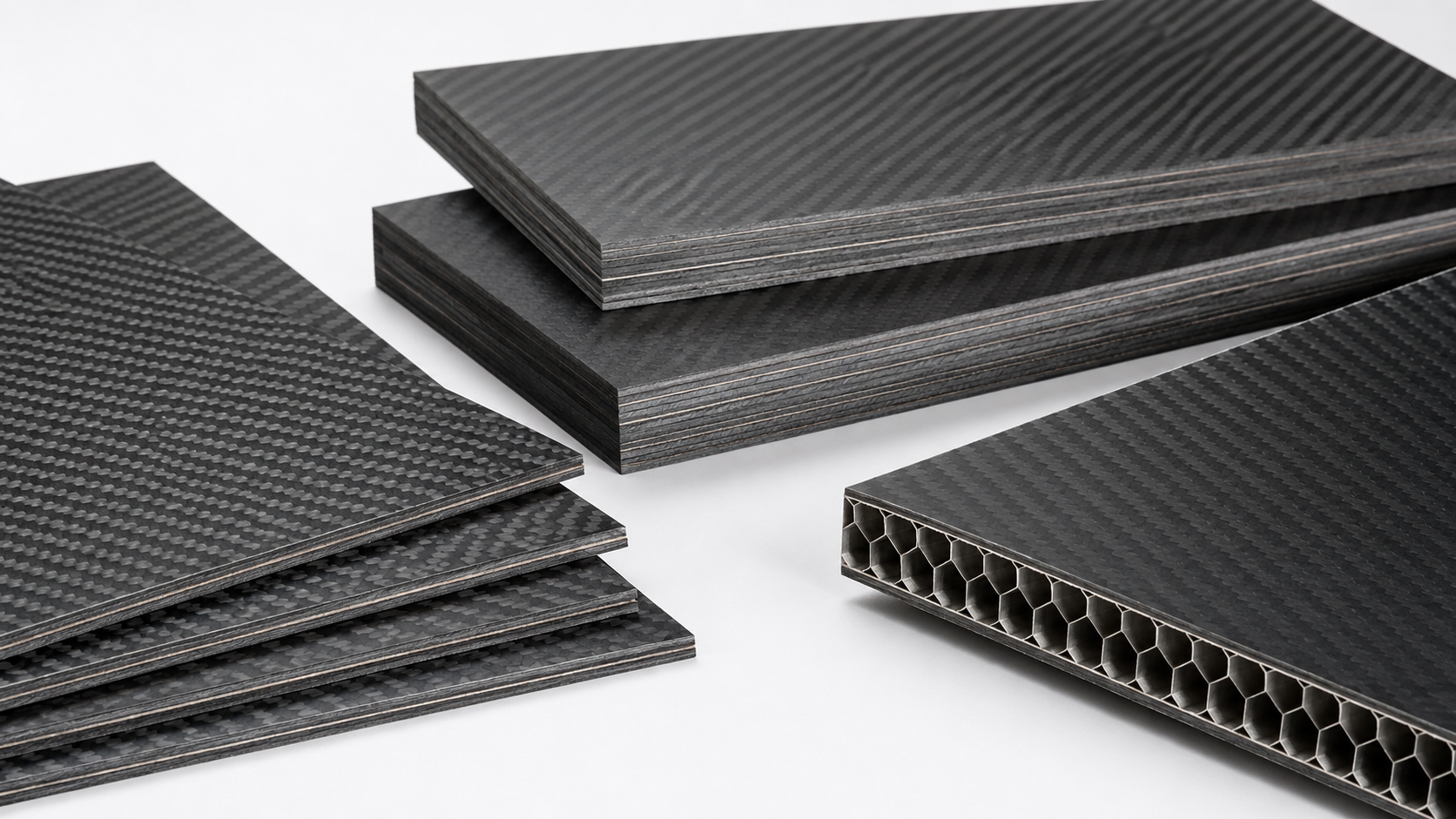
Sheets are flat laminates built from stacked plies.
Ply types include plain weave, twill, unidirectional, and quasi-isotropic laminates.
A unidirectional sheet can exceed 100 GPa of stiffness in the fiber direction. Rotate the load 90°, and that stiffness can drop below 10 GPa.
Same material.
Drastically different performance.
Why the Match Matters
Here is the critical point:
Carbon fiber strength is directional. It does not perform the same in every direction.
A pultruded tube placed under torsion depends on the resin matrix to carry shear load. Resin shear strength sits at only 10–20% of the tube’s axial capacity.
Put that tube on a drive shaft, and the failure point is built in from day one.
The form determines fiber orientation.
Fiber orientation determines where the strength is.
Pick the wrong form for your load case, and the part will not simply underperform. It can fail at a fraction of the load the buyer expected it to handle.
Step 1: Define Your Load Case Before Choosing Any Form
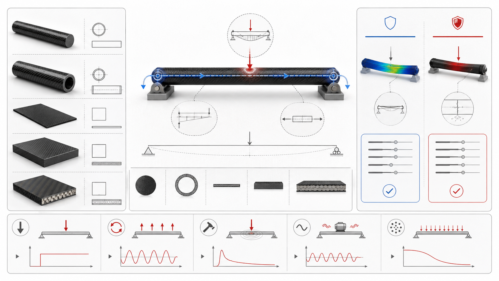
Every structural decision starts the same way.
You need to know what forces are in play before you open a product catalog.
This sounds obvious. Many teams still rush through it.
That shortcut creates real problems: a pultruded rod on a torsion-loaded linkage, a unidirectional sheet carrying load at 90° to its fiber orientation, or a flat panel selected by thickness without checking buckling or deflection.
The material is not always the problem.
The selection process was.
Four Questions to Define the Load Case
Before choosing any carbon fiber form, answer four questions:
- What type of load acts on this part?
Tension, compression, bending, torsion, shear, impact, or a combination? - Where does the load enter, and where does it exit to a support?
This tells you the real load path. - Does the design constraint focus on stiffness or strength?
Is deformation the limit, or is failure stress the limit? - Is the loading static, cyclic, or impact-driven?
Fatigue and impact can change the correct form and layup.
At HyperX Carbon, these questions come before product recommendation. A drawing without load direction often leads to an incomplete quote. A drawing plus load case gives the factory enough context to recommend a form, layup, thickness, and process route.
The Five Core Load Types
Each load type has a different structural signature.
| Load Type | Primary Stress | Key Design Metric |
| Axial tension / compression | Normal stress, σ = F/A | UTS, buckling, Pcr |
| Bending | σ = My/I | Deflection, w/L ≤ 1/250–1/500 |
| Torsion | Shear, τ = Tr/J | Twist angle ≤ 1–3° |
| Shear | τ = V/As | Shear deformation ratio |
| Combined loading | von Mises, σeq = √(σ² + 3τ²) | Dominant load identification |
Before picking a carbon fiber form, sketch the load path.
Draw a line from where force is applied to where it is constrained. Label each segment:
- Axial
- Bending
- Shear
- Torsion
- Combined
That sketch often tells you more about fiber orientation requirements than a datasheet.
The Dominant Load Rule
One practical rule:
If the dominant stress in your critical cross-section exceeds 50% of the material’s allowable, that load type governs your selection.
If stress is low but deflection is close to the limit, stiffness governs instead.
That changes the correct product form.
Get this step right, and everything downstream becomes a matching exercise.
Skip it, and you are guessing.
Carbon Fiber Rods: Pure Axial Load Applications

Solid pultruded carbon rods do one thing better than any other form:
They carry load straight along their length.
That is not a limitation.
That is the whole point.
Your load case needs to be ≥90% axial tension or compression, with bending and torsion below 10% of peak stress.
At that point, a pultruded 0° rod is usually the best structural choice. Every fiber runs along the axis. Nothing gets wasted carrying a load that is not there.
Why the Solid Cross-Section Matters
A pultruded rod has no wall to buckle.
Thin-wall tubes under compression can fail through local shell buckling or wall ovalization before the fibers reach their strength limit.
A solid rod removes that failure mode. The full cross-section carries compressive load.
That makes it more reliable in slender members where global Euler buckling — not material strength — controls the design.
The numbers support the logic.
At the fiber level, carbon tensile strength reaches 3 GPa. In a commercial pultruded rod, that translates to a composite design strength between 1,500 and 2,500 MPa in tension.
That is 3–5× aluminum at the same mass.
Where Rods Get Used
Real rod applications follow the same structural pattern:
A member connects two points, carries force between them, and does little else.
Good applications include:
- UAV and RC aircraft control linkages — push / pull rods for ailerons and rudders; load is pure axial by design
- Truss and space-frame members — tension / compression struts in robot arms, drone frames, and instrument structures
- Tie rods and tension links — machinery and fixturing applications where axial preload dominates
Where Rods Break Down
A rod fails your design the moment torsion or significant bending enters the picture.
All-axial 0° layups are the weakest option for torsion across common carbon forms.
A member that gets clamped, screwed through, or loaded sideways at its joints needs a different solution.
Switch to a roll-wrapped tube with ±45° plies — or add local overwrap reinforcement at the joint zones.
Use a solid rod when the load path is clean. Switch forms when it is not.
From HyperX Carbon’s engineering perspective, rod selection always needs joint review. Many rod problems do not start in the middle of the rod. They start where clamping, bonding, threading, or bearing stress disrupts the pure axial load path.
Carbon Fiber Tubes: Bending, Torsion, and Buckling-Critical Members
Hollow wins.
That is the structural geometry lesson engineers keep relearning.
A member under bending, torsion, or column buckling risk needs the right tool — especially where every gram counts.
Carbon fiber tubes deliver that.
The physics are straightforward: push material away from the neutral axis and you get better section efficiency with no unnecessary mass.
A tube gives far more bending stiffness per gram than a solid bar of the same material.
That is not a marketing claim.
That is second-moment-of-area math.
The density numbers make this clear:
- Carbon fiber: 1.5–1.6 g/cm³
- Aluminum: 2.7 g/cm³
- Steel: 7.8 g/cm³
Swap a steel tube for carbon fiber and you can cut component weight by up to 75% with the same cross-sectional geometry and much less mass.
Round Tube vs. Square Tube
Cross-section shape is an engineering decision, not a cosmetic one.
Round tubes spread stiffness evenly around the full circumference. That even distribution matters as soon as torsion enters the load case.
Drone arms, robotic links, and cantilever booms all face bending and torsion at the same time.
Round geometry handles both without a weak axis.
If the member might twist under load, choose round.
Square and rectangular tubes focus bending stiffness along a known axis. The principal bending direction is fixed. The part also needs to bolt flat against brackets or frames.
Square sections handle that better.
Frame structures, mounting rails, and single-plane beam applications are natural fits.
Practical rule:
Torsion present → round. Known bending axis and flat interfaces → square.
Layup Direction Controls What the Tube Can Resist
Fiber orientation inside the tube wall is where real performance gets set.
- 0° fibers carry bending stiffness and axial load. Prioritize these where beam deflection is the main constraint.
- ±45° fibers resist torsion and shear. Add these where twist angle matters — drive shafts, motor arms, or members transferring load between joints.
- 90° fibers add hoop strength, crush resistance, and diameter stability under clamping or radial compression.
A good general-purpose structural tube leads with 0° as the primary fraction, adds ±45° for torsion control, and includes 90° for local bearing and hoop stability.
Pultruded tubes drop the ±45° layer.
That is exactly why they fall short on torsion despite good bending numbers.
Lab data backs this up. A three-point bend test put a roll-wrapped carbon tube at 200 kg before failure. Stainless steel reached 175 kg. Pultruded carbon hit around 140 kg. Aluminum failed at 50 kg.
The hoop-reinforced layup also raised torsional resistance and crush strength over pultruded alternatives.
You trade a small amount of longitudinal stiffness.
That is the cost.
Where Tubes Belong in Real Structures
Carbon fiber tubes belong where deflection, twist, or buckling controls the design.
Common applications include:
- Drone arms — prop thrust, motor torque, and crash loads mix bending with torsion. Less weight also means longer flight time.
- Robot arms and cantilever booms — tubes hold deflection low at minimal mass, and high stiffness-to-weight ratio delays Euler buckling in slender members.
- Racecar and performance frames — suspension members, brake components, and chassis tubes need mass reduction and stiffness retention at the same time.
A clean, axial-only load case?
A rod may do that job better.
The moment bending or torsion enters the picture with a weight budget attached, a tube becomes the starting point.
Carbon Fiber Sheets and Panels: Area-Distributed and Shear Loads
Flat surfaces carry loads in a different way than beams.
Sheets and panels are their own design category — not a backup choice for situations where tubes and rods do not work.
Load spreading across an area calls for sheets or panels.
Single-axis load paths call for beams.
Two scenarios point toward a sheet or panel:
- In-plane membrane loads — tension, compression, and in-plane shear spread across the face
- Out-of-plane bending — distributed pressure acting across a panel surface
These two cases are not interchangeable.
Each one requires a different panel construction.
Solid Laminates vs. Sandwich Panels
A solid carbon fiber laminate handles in-plane loads well.
Fiber-direction tensile modulus runs 135–230 GPa at 60% fiber volume fraction. Tensile strength reaches 1,500–2,500 MPa, though practical design allowables land at 60–70% of that number.
For UAV decks, chassis floors, or any panel where in-plane stress makes up more than 70% of the load case, a solid laminate at 0.5–2.0 mm thickness can get the job done.
Out-of-plane bending changes the calculation.
Bending stiffness scales with Et³. Triple the thickness and stiffness increases by 27×, but mass rises with every added millimeter.
A sandwich panel gives a cleaner solution: thin carbon face sheets, typically 0.3–0.6 mm, bonded to a foam or honeycomb core, typically 5–20 mm thick.
That pushes bending stiffness up by more than 10× with very little added weight.
Quick decision rule:
- In-plane stress dominant, deflection tolerance loose, f/L ≤ 1/100 → solid laminate
- Distributed out-of-plane pressure, tight deflection limit, f/L ≤ 1/200 → sandwich panel
Fiber Orientation Follows the Load Direction
Layup sequence is not a minor detail.
It is where panel performance gets decided.
Quasi-isotropic layups like [±45/0/90]s spread stiffness across all in-plane directions. Use these when load direction shifts unpredictably, or when the panel has multiple fastener holes that move stress around specific points.
UAV decks and robot platform floors often fall into this category.
Directional layups put stiffness where the load demands it.
Wing skins along the span direction run 50–70% of plies at 0°, with ±45° and 90° layers added for shear and transverse stiffness.
Shear webs and torsion box skins flip that ratio: ±45° layers make up 60–70% of total thickness.
That is because torsion breaks down into maximum shear stress at those fiber angles.
Panels and Stiffeners
Thin panels buckle.
A sheet under 1 mm with an aspect ratio above 20:1 can hit buckling failure before it reaches its in-plane strength limit.
Adding thickness is not always the best fix.
Bond longitudinal or transverse stiffeners — hat-section, T-section, or plain strip beams — to the panel face, and local buckling resistance can rise by 3–5× at a small fraction of the mass cost.
For UAV decks, a 0.8–1.2 mm quasi-isotropic face sheet with stiffener ribs every 150–250 mm, with rib height around 15–20 mm, can carry distributed equipment loads without oversizing the laminate.
The same logic applies across applications:
Match the layup to the dominant stress direction, then check out-of-plane stability before locking final thickness.
At HyperX Carbon, panel review usually includes span, support condition, fastener zones, local reinforcement, surface requirement, and whether the buyer needs a solid laminate, ribbed panel, or sandwich construction.
Fiber Orientation as the Hidden Selection Variable
Two parts can look identical — same diameter, same resin, same surface finish — yet behave in opposite ways under load.
The difference is not on the surface.
It is inside the wall, in the angle each fiber makes relative to the stress direction.
Most selection guides skip this variable.
That is a mistake.
Carbon fiber anisotropy is strong. Unidirectional carbon fiber aligned with its load direction reaches peak tensile performance. Rotate that same sample 45°, and ultimate tensile strength drops fast.
Elongation goes up, which means the failure mode shifts — not just the numbers.
Compression strength peaks in the transverse direction and bottoms out along the panel length. Bending runs the other way: strongest along the length, weakest across it.
Same material.
Opposite structural behavior, just from changing which way the fibers point.
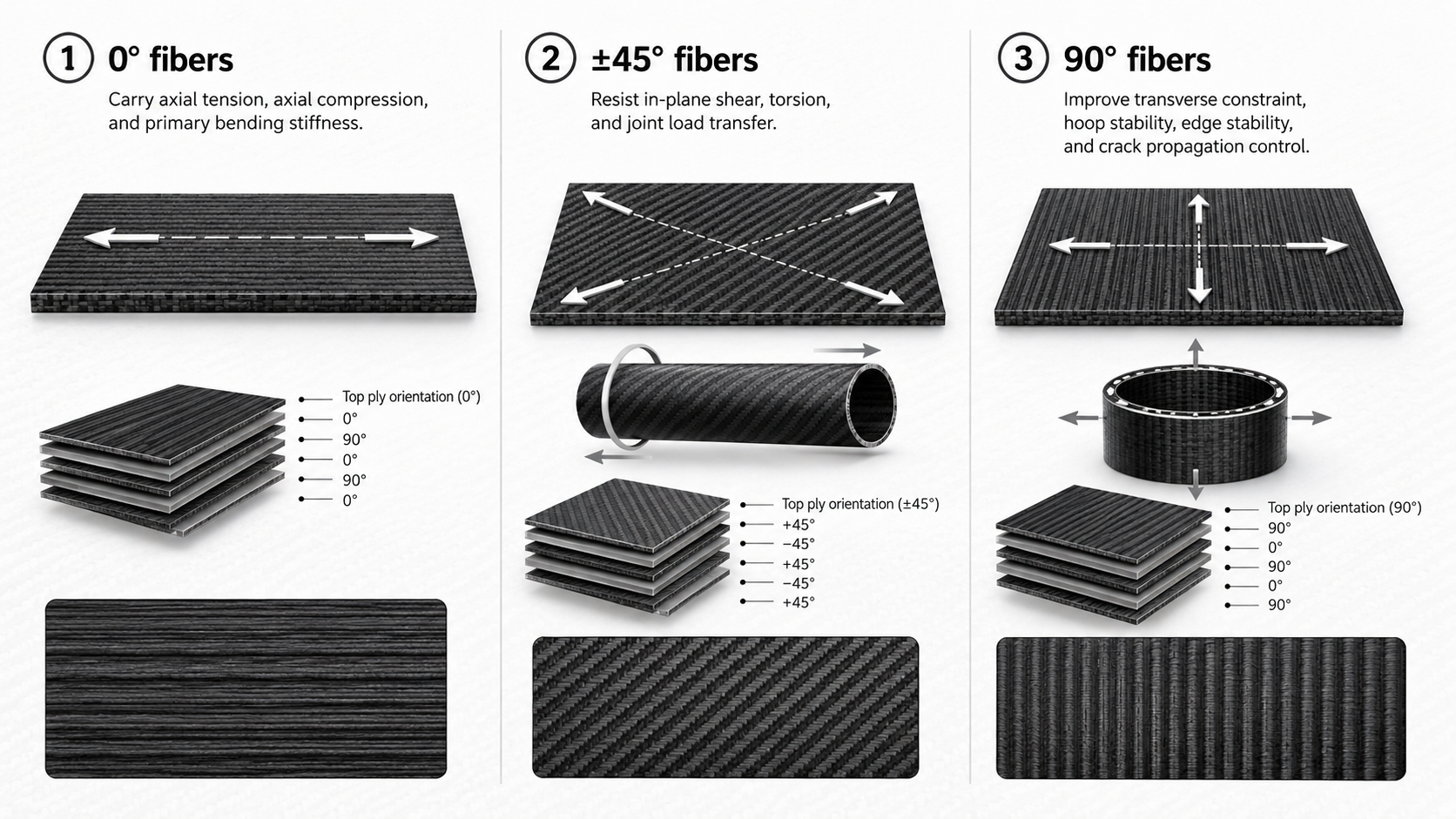
Three Orientation Rules
Three orientation rules drive most carbon fiber layup decisions:
- 0° fibers → axial tension, compression, and primary bending stiffness
- ±45° fibers → in-plane shear, torsion, and joint load transfer
- 90° fibers → transverse constraint, hoop stability, and crack propagation control
Practical Sequencing Rules
Practical sequencing matters just as much as the basic rule:
- Lock the primary load direction first — align 0° plies with the dominant tension or compression path.
- Add ±45° layers to cover shear and torsion — do not skip this if the member connects to joints or transfers torque.
- Use 90° plies to manage transverse stiffness and boundary stability.
- Do not over-build for secondary loads — extra layers for minor load contributions add weight, cost, and manufacturing complexity with little structural gain.
The goal is directional efficiency.
Not just thickness.
At HyperX Carbon, this is one of the most important engineering review points. A buyer may ask for a stronger material, but the real correction may be fiber orientation, ply balance, local reinforcement, or the product form itself.
Quick-Reference: Product Form vs. Load Case Matching Table
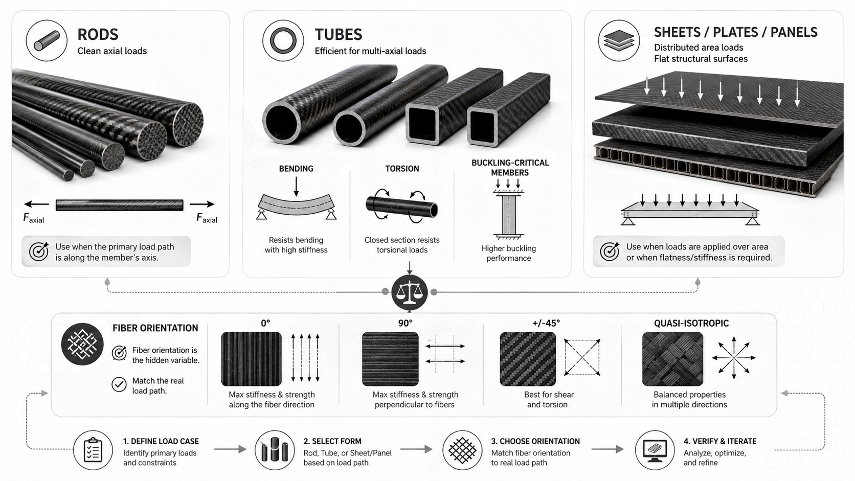
Every structural decision in this guide comes down to one practical question:
Given this specific load, which form should you order?
The table below maps each load case to a recommended product form, the fiber orientation that makes it work, and the failure mode triggered by choosing the wrong option.
| Load Case | Recommended Form | Key Fiber Orientation | Typical Application | Common Misselection & Cost |
| Pure axial tension | Pultruded rod / UD flat bar | ≥90% at 0°, Vf 55–65% | Tie rods, truss tension members, control linkages | Multi-angle fabric sheet → axial strength drops 30–50% |
| Short compression, no buckling risk | Thick-wall solid rod or quasi-isotropic laminate | 0° dominant, ≥50%; add ±45° + 90° to suppress micro-buckling | Compression blocks, bolt pad reinforcement | All-0° layup → no transverse constraint → premature fiber micro-buckling |
| Slender column, buckling-critical | Hollow closed section, round or box tube | 50–60% 0° + 20–30% ±45° + 10–20% 90° | Drone arms, truss top chord, landing gear struts | Solid rod → insufficient I → buckling load 1.5–3× lower than equivalent-mass tube |
| Pure bending | I-beam or box beam; sandwich panel for distributed loads | Flanges: ≥60–70% 0°; web: ±45° dominant | Wing spars, chassis rails, structural floor beams | Uniform flat plate, no flange → bending stiffness 30–60% lower at equal mass |
| Shear-dominant | Thin flat sheet / shear web | ±45° ≥60% total thickness | Shear webs, gusset plates, torsion box skins | All-0° web → diagonal cracking under shear, low G12 utilization |
| Pure torsion | Hollow closed round or square tube | ±45° ≥50% total thickness | Drive shafts, torque tubes, robot joint shafts | All-0° tube → torsional stiffness just 20–40% of optimized ±45° design |
| Bending + torsion combined | Roll-wrapped round tube | 0° + ±45° balanced layup | UAV motor arms, cantilever booms, suspension members | Pultruded tube, no ±45° → torsion carried by resin alone → shear failure comes fast |
| Tension + bending combined | Box or I-beam with thickened tension flange | Tension flange: extra 0° plies; web: ±45° | Landing gear beams, cantilever root zones | Tension-focused design → bending stress at flange triggers premature failure |
| In-plane multiaxial panel | Quasi-isotropic solid laminate [±45/0/90]s | Equal distribution across all in-plane directions | UAV decks, robot platforms, multi-fastener panels | Directional UD panel → 90° off-axis loads cause catastrophic ply splitting |
| Out-of-plane pressure panel | Sandwich panel, carbon face sheets + foam / honeycomb core | Face sheets: quasi-isotropic 0.3–0.6 mm; core: 5–20 mm | Structural fairings, floor panels, equipment trays | Solid laminate → bending stiffness 10× lower at same mass |
One number worth keeping in mind:
Once the dominant stress in any cross-section goes past 50% of allowable, that load type drives your form selection. Everything else is secondary.
Real-World Application Scenarios: UAV, Robotics, and Motorsport
Three industries push carbon fiber selection harder than almost any other:
- UAV development
- Robotics
- Motorsport
Each one has a distinct load signature.
Get the product form wrong, and the part fails fast.
UAV Arms: Bending and Torsion, Always Together
A quadrotor motor arm does not see clean axial load.
Motor thrust — 2–6 kgf per propeller — bends the arm outward from the frame. At the same time, motor torque between 0.5–2 N·m twists it along its own axis.
That combined loading rules out pultruded tubes entirely.
For 1–5 kg UAVs, arms are often sized at:
- OD 16–25 mm
- Wall thickness 1–2 mm
- ≥60–70% UD 0° fibers along the axis for bending stiffness
- ±45° plies in 2–4 layers through the mid-span for torsion
- 90° outer plies for hoop stability under clamp loads
A 20 mm OD arm with a [(0/±45/0/90)s] laminate at 1.5–2.0 mm wall thickness can handle 1–2 N·m motor torque.
Root and motor mount joints are where arms fail first.
Add 2–3 extra 0° plies at tube ends to raise local bending capacity by over 20%.
At bolted regions, use sleeved overwraps 2–3× tube diameter in length to spread bearing loads and prevent splitting.
For crash-prone arm tips, add a hybrid outer layer of Kevlar or Dyneema. This stops impact damage from spreading through the carbon fiber core.
The frame-level payoff is clear:
Switching from aluminum to carbon fiber tubes and sheets in drone frame redesigns delivers about 25% weight reduction with equal stiffness. That can translate to documented flight-time increases up to 33%.
UAV Decks and Robot Baseplates: Distributed Loads Need Panel Logic
A UAV deck or robot baseplate carries a very different load profile than an arm.
Distributed payload and point loads at fasteners, landing gear, and battery mounts create effective pressures of 0.1–0.5 kN/m² across the panel face.
Load direction also shifts as the platform moves.
Panel construction choice follows span, not just load size.
For span under 200 mm and moderate payload up to 2–3 kg, use a solid quasi-isotropic laminate, 1.0–2.5 mm thick, with a [0/±45/90]s layup.
The in-plane stiffness ratio E1/E2 stays near 1–1.3, which keeps the panel balanced for multi-directional loads.
For span over 200–300 mm, or a weight-critical platform, use a carbon fiber sandwich panel:
- 0.5–1.0 mm face sheets
- 5–20 mm foam or Nomex honeycomb core
- Bending stiffness 3–10× higher than a same-mass solid laminate
- Overall panel density around 150–400 kg/m³
Either way, keep maximum deflection below span/200 to span/300.
Go past that, and sensor misalignment and resonance problems become real risks.
Around gimbal mounts and LiDAR bolts, add local carbon fiber doublers 50–80 mm in diameter with 2–3 extra 0/90 plies to control contact stress.
Motorsport Suspension Rods: Pure Axial, Tightly Sized
Race suspension links — tie rods, pushrods, and toe links — carry almost pure axial load.
Peak forces reach 10–20 kN in GT cars and up to 40 kN in formula cars under hard braking and cornering.
Carbon fiber rods with tensile strength 1,500–2,500 MPa at 1.5–1.6 g/cm³ give specific strength 2–3× higher than steel at a fraction of the mass.
Sizing is direct.
Use a safety factor of 2–3× on ultimate capacity.
At a design allowable of 600–800 MPa, a 20 kN peak load needs 33 mm² cross-section — roughly a solid rod at 6.5 mm diameter.
In practice, use 8–12 mm diameters to satisfy buckling and threading requirements.
Keep L/r ratios within Euler buckling limits so the critical load stays 1.5–2× above peak compression.
The layup centers on UD 0° fibers, usually ≥80–90%. Add a small ±45° fraction for off-axis steering inputs, plus 90° hoop fibers at collar and threaded zones.
Metal end fittings need careful design.
Use tapered bonded inserts 8–12× rod diameter in length to keep interfacial shear below adhesive limits, around 15–25 MPa.
Hold adhesive layer thickness at 0.1–0.3 mm, with lap shear strength above 20 MPa.
Size bearing seats so Hertzian contact pressure stays below local crush limits. A seat diameter ≥1.5–2× rod diameter is a solid starting point.
The performance gain is real:
Cutting unsprung mass per corner by 0.5–1.5 kg through steel-to-carbon-fiber rod substitution sharpens wheel control and gives more room to tune springs and dampers.
At HyperX Carbon, these application reviews all start the same way: load type, connection method, geometry, stiffness target, and inspection requirement. The final form comes after that — not before.
The 7-Step Decision Flow: From Load Case to Final Product Specification
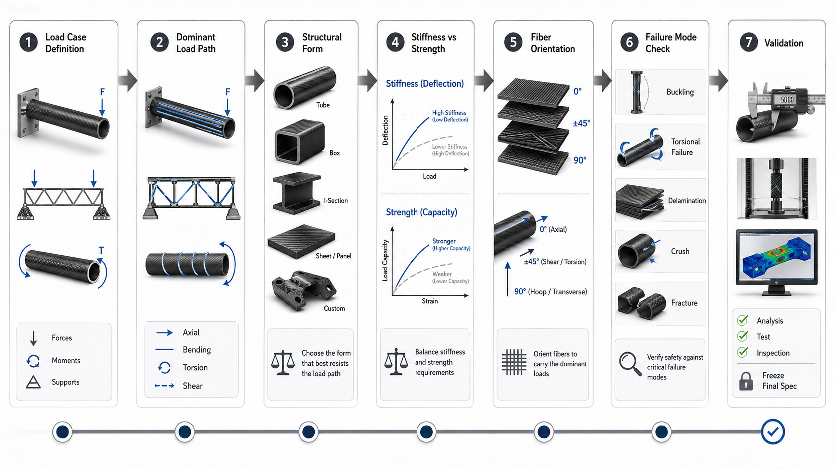
Seven steps stand between a well-specified carbon fiber part and an expensive mistake.
Work through them in order.
Each step narrows your choices before the next one begins.
Step 1: Define the Load Case
Identify force type, magnitude, direction, duty cycle, environment, and safety factor.
Note static vs. dynamic loading. Note peak vs. cyclic loading.
Skip this, and every decision after it becomes a guess.
Step 2: Identify the Dominant Load Path
Classify the main structural behavior:
- Axial
- Bending
- Torsion
- Shear
- Combined
This one step cuts out most poor-fit options before you spend money.
Step 3: Choose the Structural Form
Each load type points toward a specific shape:
- Axial-dominant → rods and tubes
- Bending-dominant → box sections or I-sections
- Torsion-dominant → closed hollow sections
- Multiaxial or distributed loads → sandwich panels or custom composite layups
Step 4: Set Stiffness vs. Strength Priority
If deflection controls function, optimize for stiffness first.
If failure load controls, lead with strength.
A part can be strong enough and still fail the application because it deflects too much.
Step 5: Assign Fiber Orientation
Place reinforcement along the principal stress directions:
- 0° for axial and bending loads
- ±45° for shear and torsion
- 90° for transverse stability
Step 6: Check Instability and Failure Modes
Check for:
- Buckling
- Delamination
- Fatigue
- Joint crushing
- Bearing stress
- Clamp damage
- Impact damage
- Local splitting
Run this check before freezing the geometry.
Not after.
Step 7: Validate, Then Freeze
FEA can screen geometry and stress concentrations quickly.
Coupon tests confirm material limits before you rely on the layup model.
Follow this progression:
Coupon data → calibrated model → component FEA → prototype test → specification freeze
One rule ties all seven steps together:
Start from the load case, follow the load path, pick the section that resists it best, lock the fiber orientation, then confirm the key failure mode before freezing the final specification.
For RFQ review, send HyperX Carbon:
- CAD file or drawing
- Load direction and load magnitude
- Static, cyclic, or impact condition
- Stiffness or deflection target
- Strength or safety factor requirement
- Part dimensions and interface locations
- Surface and tolerance requirements
- Expected quantity and production stage
With those inputs, our engineering team can review whether the project should start from a rod, tube, sheet, sandwich panel, or custom layup.
FAQ: Matching Carbon Fiber Product Form to Load Case
Can I Use a Carbon Fiber Rod Instead of a Tube?
Only if the load is mostly axial.
A rod is best when the load is ≥90% axial tension or compression and bending or torsion is below 10% of peak stress.
If torsion, side loading, clamping, or buckling efficiency matters, use a tube or add local reinforcement.
Solid does not automatically mean stronger in carbon fiber structures.
When Should I Choose a Round Tube Instead of a Square Tube?
Choose a round tube when torsion is present or load direction changes.
Round tubes distribute stiffness evenly around the circumference, which makes them better for drone arms, robotic links, cantilever booms, and torque-loaded members.
Choose square or rectangular tubes when the bending axis is known and the part needs flat mounting interfaces.
Torsion present → round. Known bending axis and flat interfaces → square.
When Is a Sandwich Panel Better Than a Solid Carbon Fiber Sheet?
Use a sandwich panel when out-of-plane stiffness is the main requirement.
A solid laminate is good for in-plane membrane loads. A sandwich panel uses thin carbon fiber skins and a lightweight core to increase bending stiffness dramatically.
Typical construction may use 0.3–0.6 mm carbon face sheets and a 5–20 mm foam or honeycomb core.
For distributed pressure and tight deflection limits, a sandwich panel can deliver more than 10× stiffness improvement with little added weight.
Why Does Fiber Orientation Matter So Much?
Carbon fiber carries load best along the fiber direction.
A unidirectional sheet can exceed 100 GPa stiffness in the fiber direction, but rotated 90°, stiffness can drop below 10 GPa.
That is why two parts with the same material, resin, size, and finish can perform very differently.
The product form gives you the shape. Fiber orientation gives you the strength direction.
What Information Should I Send Before Asking for a Recommendation?
Send the information that lets a factory engineer evaluate the part properly:
- CAD or drawing
- Application
- Load type
- Load direction
- Load magnitude
- Support points
- Stiffness or strength target
- Static, cyclic, or impact loading
- Space constraints
- Interface and joint details
- Surface and tolerance requirements
- Prototype or production quantity
A product name alone is not enough.
A good recommendation should reduce structural risk before production starts — not simply match a catalog item to a rough shape.
What Is the Main Rule for Matching Carbon Fiber Form to Load Case?
Start with the load path.
Then choose the form.
Then assign fiber orientation.
The core logic is simple:
- Rods own axial loads
- Tubes dominate bending, torsion, and buckling-critical members
- Sheets and panels handle distributed area forces and shear
- Fiber orientation multiplies or kills the performance of whichever form you choose
Get those two levers right — product form and fiber direction — and the structure is already much closer to an optimized solution.
The remaining details live in wall thickness, layup schedule, end-condition fixity, joint reinforcement, inspection, and validation.
At HyperX Carbon, we help buyers review those details before production so the final part is not just lighter, but structurally correct.
Build lighter. Build smarter. Build once.