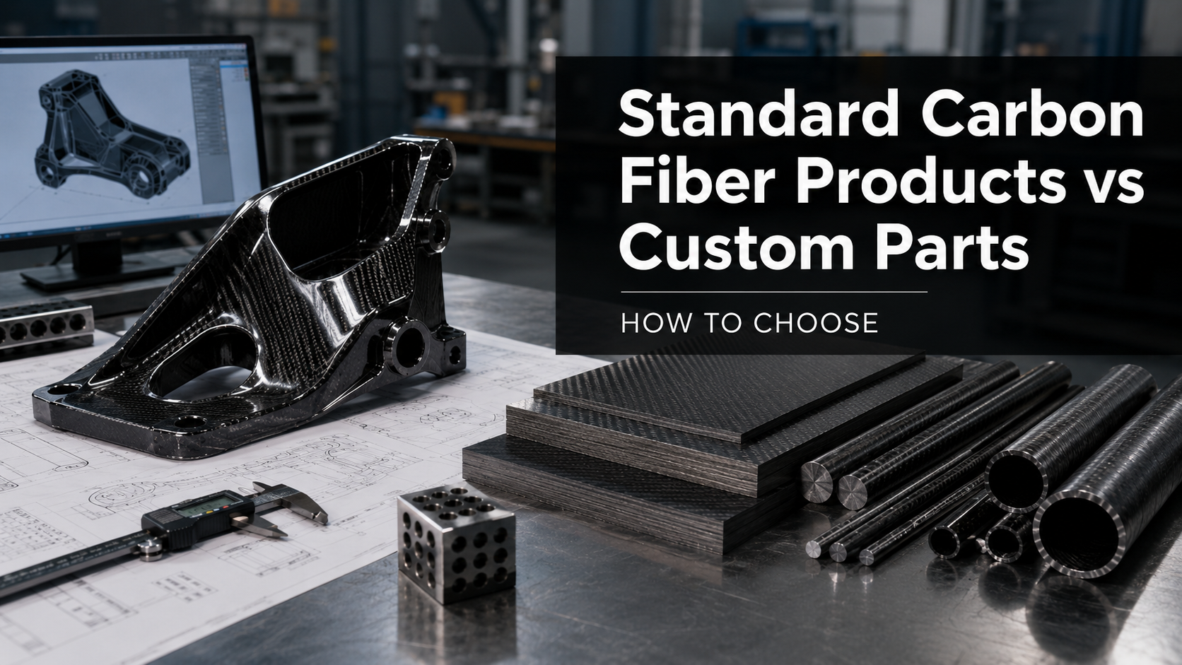
Picking the wrong carbon fiber product form can hurt your project badly.
It can weaken structural integrity, drive up costs, and force you to start over.
Flat panels for a drone frame, hollow tubes for a lightweight chassis, aerospace-grade prepreg for a precision layup — each one works differently. The gap between carbon fiber product forms is bigger than most buyers expect.
Every form has its own fiber layout, mechanical behavior, and production logic. Match those properties to your load case, and you get a high-performance build. Get it wrong, and you are looking at an expensive mistake.
This guide covers every major form — sheets, plates, tubes, rods, and prepreg. You will get the technical detail and practical clarity to make the right call the first time.
From a factory and engineering perspective, the question is not simply “which carbon fiber product is stronger?” The real question is: which carbon fiber form matches the load path, geometry, production process, inspection requirement, and budget of your project?
Carbon Fiber Product Forms Explained
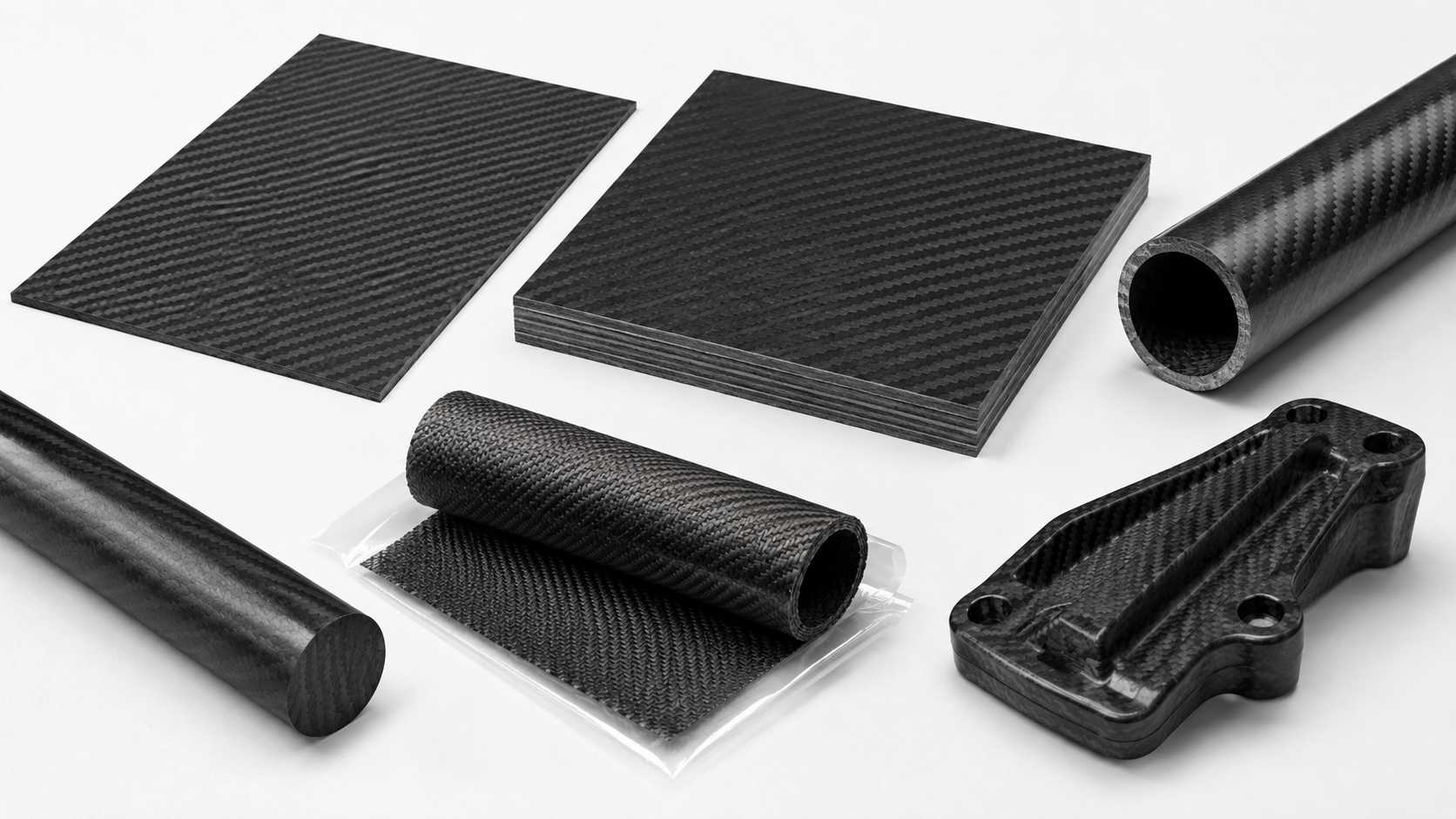
Carbon fiber is not one thing — it is a family of forms.
Each form is built for a specific structural role. This guide covers five major forms: sheets, plates, tubes, rods, and prepreg. For each one, you will find how it is made, how it behaves under load, and where it gets used.
That is the information you need to pick the right material.
| Form | Primary Strength | Typical Use |
|---|---|---|
| Sheets | Balanced in-plane properties | Panels, skins |
| Plates | Directional stiffness | Structural frames |
| Tubes | Axial load transfer | Chassis, drones |
| Rods | Compression / tension | Spars, linkages |
| Prepreg | Controlled consolidation | Aerospace layups |
Use this table as your starting point.
At HyperX Carbon, product-form review usually starts with a few engineering questions:
- What direction does the load run?
- Does the part need bending stiffness, torsional stiffness, axial strength, or surface quality?
- Will the part be CNC cut, molded, bonded, assembled, or cured from prepreg?
- Is the buyer optimizing for prototype cost, production cost, weight reduction, or structural reliability?
The right product form is not the one that sounds strongest on paper. It is the one that solves the engineering problem with the least manufacturing risk.
What Are Carbon Fiber Product Forms? (And Why the Form You Choose Matters)
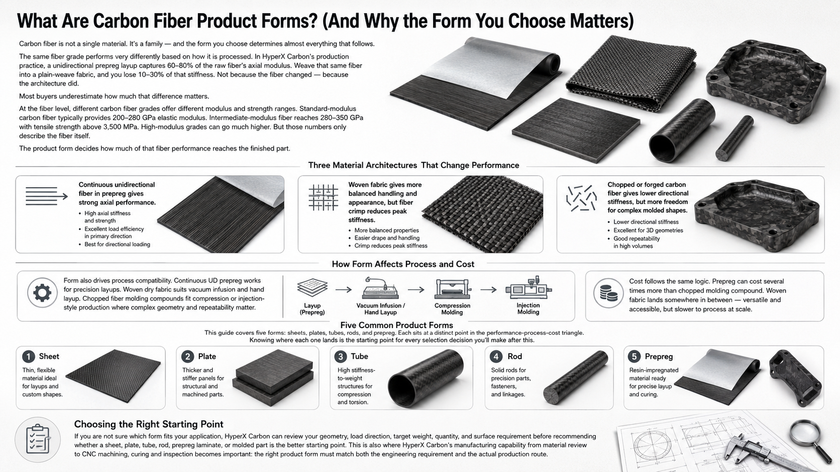
Carbon fiber is not a single material. It is a family — and the form you choose determines almost everything that follows.
The same fiber grade performs very differently based on how it is processed. A unidirectional prepreg layup captures 60–80% of the raw fiber’s axial modulus. Weave that same fiber into a plain-weave fabric, and you lose 10–30% of that stiffness.
Not because the fiber changed.
Because the architecture did.
Most buyers underestimate how much that difference matters.
At the fiber level, standard-modulus carbon, or HT grade, delivers 200–280 GPa elastic modulus. Intermediate modulus, or IM, reaches 280–350 GPa with tensile strength above 3,500 MPa. High-modulus and ultra-high-modulus grades push that range to 600 GPa and beyond.
These numbers are the ceiling — the best the fiber can theoretically offer.
The product form decides how much of that ceiling you actually reach.
Continuous unidirectional fiber in prepreg gives near-full axial strength. You get the most out of the fiber.
Woven fabric introduces fiber crimp and crossover points that cut into peak performance.
Chopped fiber molding compounds have much lower stiffness, but they are useful for complex shapes and high-volume production.
Form also drives process compatibility. Continuous UD prepreg works for automated fiber placement and precision aerospace layups. Woven dry fabric suits vacuum infusion and small-batch hand layup. Injection-grade chopped pellets fit straight into standard molding lines — high tooling cost, low per-part cost, and full geometric freedom.
Cost follows the same logic. Aerospace-grade UD prepreg can run several times the price of chopped injection compound. Woven fabric lands somewhere in between — accessible and versatile, but slower to process at scale.
This guide covers five forms: sheets, plates, tubes, rods, and prepreg. Each sits at a distinct point in the performance-process-cost triangle. Knowing where each one lands is the starting point for every selection decision after this.
For buyers, this is where many cost problems begin: the project is quoted around the wrong form before the load case and production route are fully understood.
Carbon Fiber Sheets and Plates: Flat Panel Versatility for Structural Applications

Flat panels are where most engineers first encounter carbon fiber — and where most selection mistakes happen.
The terminology creates confusion right away. “Sheet” versus “plate” sounds like a precise technical distinction. It is not. No universal thickness standard exists across the industry.
The boundary is convention, not specification.
In practice, the market treats 0.2–4 mm as sheet territory. Anything thicker — up to 38.1 mm in some specialty product families — falls into plate stock. Suppliers often use both terms within the same product line.
The label does not matter.
The physics underneath does.
Thickness Is Your Fastest Lever
Panel bending stiffness scales with the cube of thickness.
Double the thickness, and you get 8× the stiffness.
That single relationship drives most flat-panel decisions. Think about thickness first — before fiber architecture or surface finish.
Common structural ranges:
- 0.2–1 mm — overlays, skins, light-duty panels
- 1–4 mm — general fabrication, drone frames, motorsport components, automation fixtures
- 5–10 mm+ — machined blanks, structural brackets, load-bearing chassis parts
From an engineering review perspective, thickness is often the first correction point. A buyer may request a different fiber grade when the real issue is panel stiffness.
In many cases, changing thickness does more for bending stiffness than changing the carbon fiber grade.
Woven vs. Unidirectional: The Layup Decision
Once you lock in thickness, fiber architecture is the next call.
Woven fabric — twill or plain weave — distributes fibers at 0° and 90° at the same time. Load resistance stays balanced in both directions. This is the right choice for panels that face multi-directional stress, or where cosmetic quality matters.
Twill weave is the go-to for visible structural surfaces.
Unidirectional layups put all fiber strength along one axis. For load that runs in one direction — a spar, a stiffening rib, a one-way bending panel — UD construction pulls far more performance out of each unit of thickness.
The tradeoff is less tolerance for off-axis loads.
For general-purpose structural panels, the engineering default is quasi-isotropic stacking: 0° / 90° / ±45°. The 0° / 90° plies handle longitudinal and transverse load. The ±45° plies carry shear and resist torsion.
Most commercial carbon fiber flat sheet and unidirectional carbon fiber plate products follow this same logic.
Making the Right Selection
The decision chain is short:
- Load direction — one-way or multi-directional?
- Stiffness target — work backward from the t³ relationship to your thickness
- Layup — UD, 0/90 woven, or quasi-isotropic
- Finish — twill or plain weave for cosmetics; matte or gloss based on application environment
You can find commercial carbon fiber panel stock in sizes from small sheets up to 48 × 96 in blanks, with tolerances as tight as ±0.06 in.
For UAV frames, robotics, motorsport bodywork, and marine structures, 1–4 mm woven carbon fiber sheet covers most structural flat-panel needs.
At HyperX Carbon, sheet and plate discussions usually become clearer once the buyer sends the part drawing, thickness target, hole layout, surface requirement, and load direction.
A flat carbon fiber panel is not just a flat material — its thickness, layup, machining route, and finish all affect final performance and cost.
Carbon Fiber Tubes: Maximum Bending and Torsion Performance in Hollow Profiles
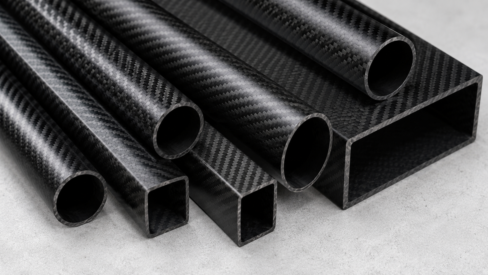
Hollow beats solid.
That is the core engineering logic behind every carbon fiber tube made today.
Nature figured this out first — bird bones, plant stems, insect exoskeletons. All hollow. All built around the same mechanical truth: material at the outer radius carries bending load far better than material at the center.
A carbon fiber hollow tube uses that geometry to the fullest. You get exceptional bending and torsional stiffness at a fraction of the weight a solid rod needs.
The math confirms it. Bending stiffness scales with the second moment of area, I. For a hollow circular section:
I = π / 64 × (OD⁴ − ID⁴)
That fourth-power relationship is the key. Push OD from 20 mm to 30 mm with the same wall thickness, and I jumps by 5×. Double the wall thickness from 1 mm to 2 mm with the same ID, and you gain about 2.3× more bending stiffness.
The geometry does the work — no extra mass needed.
Manufacturing Process: Roll-Wrapped vs. Filament Wound
How a tube is built determines what load it can handle. Two processes lead structural carbon tube production. Each performs differently.
Roll-wrapped multi-angle layup is the stronger choice for combined bending and torsion. A standard build stacks inner 0° axial plies, middle ±45° torsion plies, and outer 90° hoop plies.
In direct three-point bend testing, a roll-wrapped tube hits a failure load near 200 kg. That beats 175 kg for stainless steel of the same size, and 140 kg for a pultruded carbon tube.
The multi-angle ply structure gives it strong resistance to both bending and twisting.
Filament-wound tubes use helical ±θ winding patterns. They perform best under torsion and internal pressure. For drive shafts and torque-heavy applications, filament winding is the natural fit.
Cost follows process complexity:
- Pultruded — lowest cost, near-100% 0° fiber, continuous process
- Roll-wrapped / filament wound — 20–50% higher due to multi-angle layup and tooling
In structural applications where bending and torsion matter, that price difference is worth it.
This is one of the key engineering pain points buyers face: the cheapest tube may not be the correct tube. A pultruded tube can be economical, but if the part sees torsion, clamp load, side load, or repeated bending, the layup and process matter more than the product name.
Fiber Angle: The Performance Control Knob
Fiber orientation inside a tube is not a minor detail — it is the main design variable.
Three angles, three jobs:
- 0° axial fibers carry tension, compression, and bending stress along the tube length. A 100% unidirectional 0° tube gets closest to the theoretical tensile limit of the fiber itself.
- ±45° fibers handle shear and torsion. Torque-heavy applications — robotic joints, drive shafts — need ±45° content above 30–40% fiber volume.
- 90° hoop fibers resist internal pressure, radial loads, and localized crushing at clamp points.
Practical layup ratios by load case:
| Load Case | 0° | ±45° | 90° |
| Bending + axial | 60% | 20% | 20% |
| Torsion dominant | 30% | 50% | 20% |
| Axial tension / compression | 80% | 10% | 10% |
Fiber angle is not a cosmetic specification. It is the performance control knob inside the tube.
Cross-Section Shape and Application Matching
Round tubes spread bending and torsion in all directions at equal levels. That makes them the right pick where load direction changes.
Square and rectangular hollow sections carry more bending stiffness in a fixed plane, but they give up torsional balance.
Common application benchmarks:
- Drone arms, 4–8 kg UAV class: OD 16–25 mm, 1–2 mm wall, roll-wrapped with 0°:±45°:90° around 50:30:20. The 90° outer layer stops clamp crushing at motor mounts.
- Camera booms and jibs: OD 25–40 mm, 1.5–2.5 mm wall. High 0° content handles bending stiffness. The ±45° plies cut torsional vibration during movement.
- Bicycle frame tubes: OD 30–45 mm, 0.7–1.2 mm wall on high-end road frames. Bottom bracket zones use heavy ±45° for torsional rigidity. Top tubes stay 0°-dominant for axial and bending control.
Start your tube selection with OD — it moves the stiffness number the most. Then set wall thickness and fiber angle to match the exact load your application puts on the tube.
At HyperX Carbon, tube selection is usually reviewed around OD, wall thickness, fiber angle, clamp zones, assembly method, and load direction.
If the buyer only provides an outer diameter and length, the engineering picture is incomplete.
Carbon Fiber Rods: Unmatched Axial Stiffness for Linkages, Spars, and Structural Members

Rods are the specialists of the carbon fiber world — built for one job, and hard to beat at it.
Pultrusion pulls continuous fibers through resin and a heated die in a single, linear process. The result: 85–95% of fibers aligned along the rod axis.
That near-perfect axial alignment is the core reason pultruded carbon fiber rods deliver stiffness numbers other forms cannot match for straight-line load paths.
What the Numbers Look Like
Standard commercial pultruded rods fall in this range:
- Density: 1.30–1.50 g/cm³
- Longitudinal tensile modulus: 28–40 GPa
- Tensile strength: 400–500 MPa
- Compressive strength: 200–320 MPa
Higher-end engineering grades go much further — modulus 150–250 GPa, tensile strength 1,500–2,500 MPa.
The gap between grades is real. For precision structures where deflection must stay near zero, choose your grade to match that requirement.
Fiber volume fraction matters just as much as grade. Target 60–70% FVF in structural pultrusions. Drop below that threshold and stiffness and strength fall off in a direct, linear way — not a slow taper, but a sharp drop.
For carbon fiber rods, the value comes from axial fiber alignment, grade selection, and fiber volume fraction.
Where Rods Belong and Where They Do Not
Use a rod when the load is axial.
Tie rods, control linkages, spars, sensor masts, antenna booms, structural braces — any application where the force runs straight along the member’s length. Carbon rods also perform well in corrosion-sensitive environments: civil retrofits, pre-tensioned tendons, marine frameworks.
Switch to a tube when torsion enters the picture.
A hollow section places material farther from the neutral axis, using the same mass more efficiently. Torsional and bending efficiency both go up.
A pultruded rod under significant side load or clamp crushing is the wrong tool for the job.
One practical design rule: members that see high torsion or hoop load belong in a roll-wrapped, filament-wound, or braided tube — not a solid rod.
This is a common customer pain point. A rod may look stronger because it is solid, but in bending or torsion, it can be the less efficient choice.
Solid does not automatically mean stronger in carbon fiber structures.
The Brittleness Problem
Carbon rods do not bend before they break.
Elongation at break runs 1.2–1.8% — sudden failure, no warning. Small manufacturing flaws or impact events can cut load capacity by 30–50%. Visual inspection misses most of it.
For structural applications, ultrasonic C-scan is the inspection method that finds subsurface damage reliably. Do not skip it.
Design the joint with care too. Pair rods with bonded metal end fittings or inserts — let the carbon carry axial load, and let the fitting handle clamping and bearing stress.
That division of labor protects both parts.
From a manufacturing standpoint, many rod failures begin at the joint, not in the middle of the rod. HyperX Carbon reviews rod applications around axial load, fitting design, clamping method, bonding area, and inspection needs before recommending a rod-based solution.
Carbon Fiber Prepreg: Precision-Engineered Material for High-Performance Structures
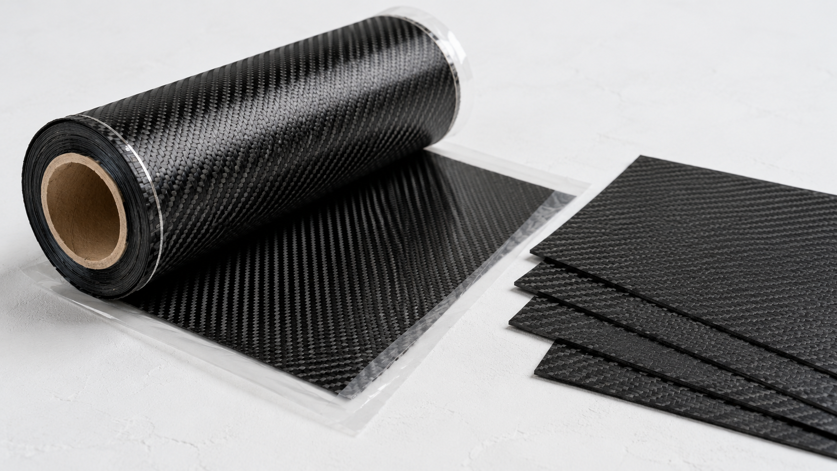
Prepreg carbon fiber material is not a shortcut — it is a controlled system.
Every variable that ruins a wet layup gets solved before the material reaches your shop floor.
The defining feature is the B-stage resin state. Raw liquid resin, or A-stage, reacts until it solidifies into a handleable sheet — but stops short of full cure. Around 10–80% of epoxy functional groups have reacted. The rest sit dormant, waiting for heat to finish the job.
That partial reaction is what gives prepreg its shelf life, tack, and consistency.
Resin Control: Where Prepreg Earns Its Price Premium
In a wet layup, resin-to-fiber ratio drifts ±5–10 wt% between operators and batches. Prepreg holds that variance to ±2–3 wt%, with fiber volume fractions locked at 55–60%.
That precision gives you predictable stiffness and strength — batch after batch.
The manufacturing process is what makes that possible. Fiber tows move through a resin bath in one continuous pass. A metering system removes excess resin. Then a heated oven drives partial polymerization.
You get a uniform sheet with controlled thickness and consistent chemistry throughout.
Prepreg earns its price premium through resin control, fiber volume control, and repeatability.
Cure Process: Oven vs. Autoclave
Two routes exist — and they produce noticeably different results.
Vacuum bag + oven hits typical void content of 1–2%. That is solid for racing bodywork, bicycle frames, and secondary structures. Equipment cost stays low.
Autoclave applies 0.4–0.7 MPa of external pressure alongside full vacuum. Void content drops to <0.5%. Interlaminar shear strength and fatigue life improve by 10–30% over oven-cured parts.
This is the aerospace standard. It is also why autoclave-cured tensile strength can reach 2,000–2,800 MPa with modulus at 130–180 GPa.
The cost is real. Large autoclave vessels run into the millions. Full cure cycles take 6–8 hours. Cold storage adds logistics burden too — shelf life at 0–5°C runs 6–12 months, with just 7–30 days of out-life at room temperature.
Prepreg: The Right Material for High-Stakes Builds
Use prepreg carbon fiber material where structural reliability is non-negotiable: aerospace primary structures, UAV airframes, motorsport monocoques, high-cycle fatigue applications.
The performance gap over dry fiber systems — especially in compression and interlaminar strength — justifies the material cost, $80–200/kg for aerospace-grade, and the process investment.
A failed spar or a delaminated panel under load costs far more.
That margin is not expensive. It is cheap.
At HyperX Carbon, prepreg is not treated as a prestige choice. It is treated as a risk-control choice.
If the application does not need prepreg-level repeatability, another form may be more cost-effective. If failure risk is high, prepreg can be the more economical decision over the full project lifecycle.
Carbon Fiber Product Forms Comparison: Performance, Cost, and Machinability at a Glance
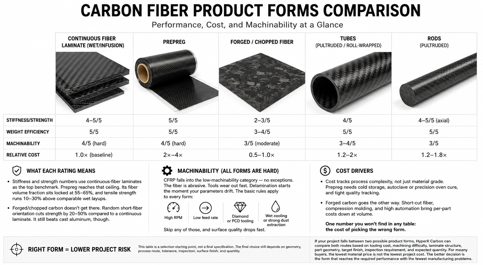
Five forms. Five very different trade-offs.
Here is what the numbers look like side by side.
| Form | Stiffness / Strength | Weight Efficiency | Machinability | Relative Cost |
| Continuous fiber laminate, wet / infusion | 4–5 / 5 | 5 / 5 | 4 / 5, hard | 1.0× baseline |
| Prepreg | 5 / 5 | 5 / 5 | 4 / 5, hard | 2×–4× |
| Forged / chopped fiber | 2–3 / 5 | 3–4 / 5 | 3 / 5, moderate | 0.5–1.0× |
| Tubes, pultruded / roll-wrapped | 4 / 5 | 5 / 5 | 3–4 / 5 | 1.2–2× |
| Rods, pultruded | 4–5 / 5 axial | 5 / 5 | 3 / 5 | 1.2–1.8× |
What Each Rating Means
Stiffness and strength numbers use continuous-fiber laminates as the top benchmark. Prepreg reaches that ceiling. Its fiber volume fraction sits locked at 55–65%, and tensile strength runs 10–30% above comparable wet layups.
Forged and chopped carbon do not get there. Random short-fiber orientation cuts strength by 20–50% compared to a continuous laminate. It still beats cast aluminum, though.
Machinability is hard across every carbon fiber form. CFRP falls into the low-machinability category — no exceptions. The fiber is abrasive. Tools wear out fast. Delamination starts the moment your parameters drift.
The basic rules apply to every form:
- High RPM
- Low feed rate
- Diamond or PCD tooling
- Wet cooling or strong dust extraction
Skip any of those, and surface quality drops fast.
Cost tracks process complexity, not just material grade. Prepreg needs cold storage at −18°C, autoclave or precision oven cure, and tight quality tracking. That is the source of its 2×–4× price premium.
Forged carbon goes the other way. Short-cut fiber, compression molding, and high automation bring per-part costs down at volume.
One number you will not find in any table: the cost of picking the wrong form. That is always the most expensive mistake.
For buyers, this comparison should not be used as a generic ranking. It should be used as a decision filter.
The best carbon fiber form is the one that delivers the required performance without forcing unnecessary tooling, processing, machining, or inspection cost.
How to Choose the Right Carbon Fiber Form for Your Project: A Decision Framework
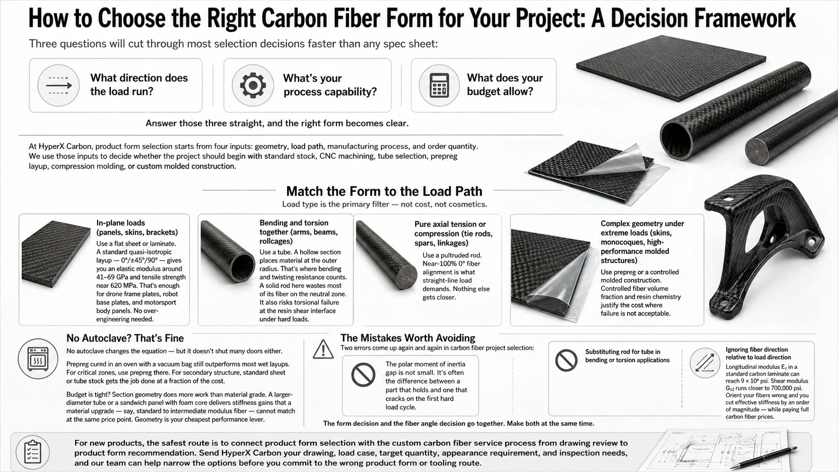
Three questions will cut through most selection decisions faster than any spec sheet:
- What direction does the load run?
- What is your process capability?
- What does your budget allow?
Answer those three straight, and the right form becomes clear.
At HyperX Carbon, we usually add a fourth practical question:
What information is missing before a safe recommendation can be made?
A product form cannot be selected properly from a product name alone. The application, load path, geometry, tolerance, surface requirement, process route, and production volume all affect the correct answer.
Match the Form to the Load Path
Load type is the primary filter — not cost, not cosmetics.
In-plane loads, such as panels, skins, and brackets: use a flat sheet or laminate. A standard quasi-isotropic layup — 0° / ±45° / 90° — gives you an elastic modulus around 41–69 GPa and tensile strength near 620 MPa. That is enough for drone frame plates, robot base plates, and motorsport body panels. No over-engineering needed.
Bending and torsion together, such as arms, beams, and rollcages: use a tube. A hollow section places material at the outer radius. That is where bending and twisting resistance counts. A solid rod here wastes most of its fiber on the neutral zone. It also risks torsional failure at the resin shear interface under hard loads.
Pure axial tension or compression, such as tie rods, spars, and linkages: use a pultruded rod. Near-100% 0° fiber alignment is what straight-line load demands. Nothing else gets closer.
Complex geometry under extreme loads, such as aerospace skins and monocoques: use prepreg. Controlled fiber volume fraction and resin chemistry justify the cost in structures where failure is not acceptable.
No Autoclave? That Is Fine
No autoclave changes the equation — but it does not shut many doors.
Prepreg cured in an oven with a vacuum bag still outperforms most wet layups. For critical zones, use prepreg there. For secondary structure, standard sheet or tube stock gets the job done at a fraction of the cost.
Budget is tight?
Section geometry does more work than material grade.
A larger-diameter tube or a sandwich panel with foam core delivers stiffness gains that a material upgrade — say, standard to intermediate modulus fiber — cannot match at the same price point.
Geometry is your cheapest performance lever.
The Mistakes Worth Avoiding
Two errors come up again and again in carbon fiber project selection.
Substituting rod for tube in bending or torsion applications. The polar moment of inertia gap is not small. It is often the difference between a part that holds and one that cracks on the first hard load cycle.
Ignoring fiber direction relative to load direction. Longitudinal modulus E₁ in a standard carbon laminate can reach 9 × 10⁶ psi. Shear modulus G₁₂ runs closer to 700,000 psi. Orient your fibers wrong and you cut effective stiffness by an order of magnitude — while paying full carbon fiber prices.
The form decision and the fiber angle decision go together. Make both at the same time.
What to Send Before Asking for a Recommendation
If you are not sure which carbon fiber form fits your project, do not start with only a product name.
Send the information that lets a factory engineer evaluate the part properly:
- Application
- Part drawing or CAD file
- Maximum dimensions
- Expected load direction
- Bending, torsion, axial, or impact requirement
- Thickness, OD, ID, or wall thickness target
- Surface requirement
- Tolerance requirement
- Prototype quantity
- Annual volume
- Whether the part will be machined, bonded, molded, or assembled
With those inputs, HyperX Carbon can help narrow the choice between sheet, plate, tube, rod, prepreg, or a custom composite structure.
A good recommendation should reduce risk before production starts — not simply match a catalog item to a drawing.
Frequently Asked Questions About Carbon Fiber Product Forms
These questions come up on every serious carbon fiber project. Here are straight answers.
What Is the Actual Difference Between Prepreg and Dry Carbon Fiber?
Prepreg arrives with resin already metered into the fiber at the factory. The resin content is controlled at the source, consistent batch to batch.
Dry carbon fiber comes without resin. You add it yourself through wet layup or vacuum infusion.
That difference matters. Prepreg holds resin content variance to ±2–3 wt%. Dry fiber results depend on your process. One operator does it well; another does not. The results diverge.
Performance follows the same split. Prepreg gives you lower void content, better fiber packing, and stronger mechanical properties. Dry and infused parts can be strong — but your process has to be tight.
Choose prepreg when repeatability and peak performance are non-negotiable. Choose dry fiber when cost control and process flexibility matter more.
How Do You Cut Carbon Fiber Plates and Tubes Without Wrecking Them?
Four rules keep the cut clean:
- Fine-tooth carbide blade only. Coarse blades cause delamination and fraying fast.
- Support both sides of the cut. Unsupported panels chip and break out at the edge.
- Moderate feed pressure. Forcing the tool builds heat. Heat damages the resin matrix.
- Dust extraction plus full PPE. Carbon fiber dust is abrasive, conductive, and hazardous to breathe.
For drilled holes, start with a small pilot hole. Step up to final diameter from there. Back the exit side with a sacrificial board to eliminate tear-out.
From a factory perspective, cutting quality is not just a workshop detail.
Poor cutting can turn a good carbon fiber form into a rejected part. Machining route, tool selection, workholding, and dust extraction should be reviewed before production.
How Much Lighter Is a Carbon Fiber Tube Compared to Aluminum?
At equivalent bending stiffness, carbon fiber tubes are 50–70% lighter than aluminum.
A mass reduction of 2× to 4× is a realistic target — that is what you get when replacing aluminum tube with a well-specified carbon equivalent.
The exact number depends on diameter, wall thickness, fiber orientation, and the specific load case. There is no single answer — but the direction is always the same.
A well-specified carbon fiber tube can reduce weight significantly, but only when the geometry and layup match the load.
Which Fiber Direction Should I Use: UD, Woven, or Quasi-Isotropic?
UD: maximum stiffness along one axis. Right for beams, spars, rods, and any application where load runs in a clear, single direction.
Woven: better drape, easier handling, more balanced edge robustness. The trade-off is a small drop in peak axial stiffness due to fiber crimp at weave crossings.
Quasi-isotropic: in-plane properties stay close to equal in all directions. The right call for mixed or unpredictable loads — at the cost of lower peak performance on any single axis.
Load direction tells you which one to use.
Map the load first. The answer usually becomes clear.
Conclusion
Picking the right carbon fiber product form matters more than most buyers think.
It is the decision that decides whether the finished part performs at its best — or falls short.
Sheets and plates give you flat-panel freedom. Tubes offer strong bending rigidity at very low weight. Rods lock in axial stiffness where other materials cannot compete. Prepreg gives aerospace-grade control over every layer of the laminate.
Each form has a specific job.
The engineering task is to match that job to the real load case, process route, budget, and production requirement.
Take your application requirements and run them against the comparison framework in this guide. Narrow your options down to one or two candidate forms. Then browse HyperX Carbon’s full range of carbon fiber composite forms. Specs, dimensions, and material grades are all listed there.
If the choice is still unclear, send HyperX Carbon your drawing, dimensions, load direction, target stiffness, surface requirement, tolerance requirement, quantity, and application background.
Our engineering team can help review whether sheet, plate, tube, rod, prepreg, or a custom composite structure is the right starting point.
The right form is out there.
Do not build around the wrong one.